diy solar

diy solar

Growatt 12kw Help ~ JK BMS Throwing "Discharge Short Circuit Protection"

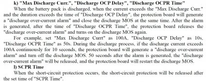
The manual is basically no help. It total skips any mention of the Short Circuit Protection Delay in the description. It mentions the release time, then refers you to the end where it lists the optional settings for each.
 
Last edited:
In a second copy of the manual I have, it does not even mention the Short Circuit Protecion Delay. I just mentions the release time. The description should have occurred between the OCP and the SCPR settings. Its not even in this manual. Not even in the back discussing the range of settings.

OCPR.JPG
 
The BMS is rated for 200 amps and has a setting for
- Over Current Discharge. Set to 200 amps
- Short Circuit Protection Delay. Set to 1850 microseconds (the manual says it can be set to "Off" but gives no explanation
- Short Circuit Protection Release. Set to 60 Seconds. (And it works because it counts down and then the BMS powers back up. )

Note: The BMS itself is not powering down when shuts off power from the batteries. I am staying connected to it via bluetooth and can monitor release time

But I am confused. Is this short something that is happening inside the BMS due to over current, or is it something in my wiring (which I should be able to discover if I break it down to the simplest connection ... or it is inside the inverter. )

But if it is internal of the BMS and being cause by over current, why would the error not be the Over Current Discharge? Seems odd that is not what is shutting the system down. The error log is just Short Circuit Protection.

I can try to slooth it out, just need to know what I might be looking for?

over-current and short circuit both trigger on amps through the bms.
The over-current trigger will be lower amps for a longer duration.
The short circuit trigger will be considerably higher amps and a much shorter time duration.
We know the time duration is 1500 microseconds.
I want to know how many amps it takes to make the current criteria.
 
over-current and short circuit both trigger on amps through the bms.
The over-current trigger will be lower amps for a longer duration.
The short circuit trigger will be considerably higher amps and a much shorter time duration.
Thanks, That makes sense now.

We know the time duration is 1500 microseconds.
I want to know how many amps it takes to make the current criteria.

How would I determine this?
 
When you get a reproducible scenario you can put your clamp meter on the inverter.dc.positive lead and use the max function to see how much amperage is being drawn.
I see you have a cl-390 same as me.
Mine sucks for dc voltage but its a pretty good clamp meter.
Its rated to 400 amps.
Since your Growatt is so heavy I suspect its a low frequency inverter with significant surge capacity.
I wonder if the clamp meter will off scale high.
 
Last edited:
When you get a reproducible scenario you can put your clamp meter on the inverter.dc.positive lead and use the max function to see how much amperage is being drawn.
I see you have a cl-390 same as me.
Mine sucks for dc voltage but its a pretty good clamp meter.
Its rated to 400 amps.
Since your Growatt is so heavy I suspect its a low frequency inverter with significant surge capacity.
I wonder if the clamp meter will off scale high.
Yes it is hi frequency.

And yes that is my meter.

I also have a clamp on inrush meter. But I am not sure how accurate it is.
 
Technically you should have a 400 amp fuse on the inverter positive as close to the busbar as possible.
 
Technically you should have a 400 amp fuse on the inverter positive as close to the busbar as possible.
I realize this. I intentionally undersized the fuses to protect the BMS's. Might not have been my best idea. But you can see in my Battery Drawing, I originally planned for 400 amp Class T Fuses.
 
I did find this in another discussion. Same error. Same BMS. But I think the OP was having the error in charging. But regardless, RCinFLA suggests raising the Delay. Not sure I understand how much? the default is 1500 and I have mine set at 1850 now and it is working. Not sure if he is saying raise it in 500 increments not to exceed 5000 to 8000?

Also he says he reached out to JK about the current spec, I do not think he has heard back

 
I realize this. I intentionally undersized the fuses to protect the BMS's.
You have it backwards.
BMSs protect fuses.
Might not have been my best idea. But you can see in my Battery Drawing, I originally planned for 400 amp Class T Fuses.
I meant a 400 amp fuse on the inverter circuit not the battery circuits.
This meter. Probably not the best

Mastech MS2108 True-RMS AC/DC Clamp Meter with Inrush Current Measurement https://a.co/d/0p4GHFU
Clamps are passive devices so you do both at the same time.
I like my Mastech meter.
The manual says its good for 600 amps dc.

I'm going offline.
 
I think this message indicates the root cause.
 
Are you suggesting I also need a 400 amplifier fuse besides the two 225 Amp fuses? And to place it between the battery busbar and inverter on the 4/0 cable positive?

I can do that
 
Are you suggesting I also need a 400 amplifier fuse besides the two 225 Amp fuses? And to place it between the battery busbar and inverter on the 4/0 cable positive?
Yes.
 
Back
Top