John Frum
Tell me your problems
- Joined
- Nov 30, 2019
- Messages
- 15,233
@MrM1 according to @RCinFLA
"Messages seem to indicate the BMS is passing too much load current.
There are ten parallel chip resistors of 1 milliohm each that are for current shunt sensor reading. If one or more of these goes open for any reason the result is higher net shunt resistance with microcontroller ADC reading a higher voltage drop across shunt and calculating a higher current than actual."
Assuming I understand this correctly, my summary of the above is...
The BMS current sensor on one or both BMSs is/are erroneously reading too high.
lets test this hypothesis.
Because we can we are also going to compare the accuracy of both of your clamp meters.
For a test, run a large resistive load off of the inverter.
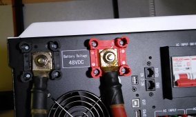
Measure dc current on the inverter branch circuit using both clamp meters.
To get a good measurement put the clamp meter in dc amps mode and put the clamp on its side so both jaws touch the wire and then zero it.
The put it around the wire to get a measurement.
Do this with both clamp meters and record the measurements.
Hope fully the meters read close to the same.
Now take a measurement on each of the battery feeder circuits.
The sum of the measurements on the feeder circuits should tally with the measurement on the inverter circuit.
Now compare the feeder measurements with the BMS current measurement.
If they hypothesis is correct one or both of the BMS will be reading higher than the clamp meters.
Report back with all measurements.
Last edited:


