diy solar

diy solar

Growatt 12kw Help ~ JK BMS Throwing "Discharge Short Circuit Protection"

MrM1

I'm Here, But I'm Not All There
Joined
Mar 1, 2021
Messages
2,422
Location
N. Central FL
I saw something like this in a recent thread, but I think the OP said it had to do with charging and I did not want to hi jack the thread.

Here is the scenario,
- JK/Heltec 200 amp BMS with 2 amp Balancer
- Growatt 12kw off grid inverter
- 16s (x2) EVE 280 cells = 48v
- SOC is about 78%
- System mounted/Installed in a Cargo Trailer. Battery negative connected to trailer frame as well as AC ground

Fault:
System was working off grid at about 1500 watts
Trying to start a 3 Ton AC
Whole house goes dark
At first I thought it was the inverter Shutting down on an LVC (Low Voltage Cutoff)

But then when I went out and repeated the shut down I see I am getting this error from Both BMS's
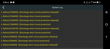
BMS Short Circuit Protection.jpg

Both the Same. So it is in the BMS

Here is what is Odd. As noted above, I have the whole system mounted in a Cargo Trailer. After discussing things with @FilterGuy I decided to ground the (-) Negative Battery Cable / Terminal AND the AC ground to the trailer frame. There is no earthing for this set up in the trailer, but earth ground does exist in the main panel outside the trailer that is being fed by the AC output of the inverter.

Here is what is Odd. 5 days ago, Before I grounded the Battery Negative to the trailer frame, I was able to start the 3 Ton AC. No problem. Now tonight every time it tries to start I get the above error. The system will start my 1 Ton AC, But not the 3 Ton AC. So I thought maybe the compressor was locked.

But here's the thing. I am getting 47v DC when I touch the Battery (+) positive and the trailer frame. AND ... I am getting 47v DC EVEN when I disconnect the battery negative from the frame (leaving the AC ground connected.

BUT WHAT'S REALLY WEIRD, I AM able to start the 3 Ton AC no problem with the Battery (-) Negative ground to the trailer disconnected.

Neither BMS throws the error. Any idea what is going on?
 
Well Scratch that .... It just shut down both BMS' with the "Discharge Short Circuit Protection" error when it just tried to start the 3 ton AC, EVEN WITH the Negative Battery terminal NOT connected / grounded to the trailer frame.

But why am I seeing 47v DC between the trailer frame and the battery (+) positive? Getting the even when the inverter is off. As far as I know there is not connection between the battery (+) or (-) and the frame.
 
When I try to hunt things down, I temporarily isolate things down to the simplest. Piece by piece bringing things back till bad circuit is found. Is the problem the vehicle side or trailer. Divide, localize and conquer.
 
When I try to hunt things down, I temporarily isolate things down to the simplest. Piece by piece bringing things back till bad circuit is found. Is the problem the vehicle side or trailer. Divide, localize and conquer.
Not likely possible a cell rubbed thru. Possibly a cable though. I'm guessing I should not have 47vdc between trailer Frame and battery positive? (battery itself is at 52.4vdc)

There is no vehicle connect to the trailer at this time. Plan to start taking things down this morning to see if I can find the short
 
The growatt inverter is passing 49vdc through the invert AC out on L1 / L2 and neutral when the inverter is off
 
I read this and your previous linked post just now. Looks really GREAT, Seriously, that IS ART ! Well Done and thought out and planned... But I see one issue possibly, is the weight distribution that will likely have an effect on handling when it transit, The combined cells on one side is Seriously heavy compared to the other side, this may come back to bite you. The other point is when you actually have all 5 Packs built for the Bank that weight & centre of gravity will create a bias, which you will encounter when turning. It may have been more prudent to divide that weight and put it low (centre of gravity issue).

The Home:
I'm certain that the house VAC System is properly Grounded to Earth with Rods or Plates most likely close to the main panel as required by code. When you plug in the VAC Connection to the house, it uses the "House Ground" and that is fine. Grounding issues are a bit complicated and far too many "opinions" are out there, ALWAYS defer to the Electrical Code !

I could get into a Long & Drawn out discussion here BUT if you read these Whitepapers from Samlex America, they explain this in detail and it is to NEC Requirements. Read these before doing anymore lest you suffer dire consequences.
BTW: just cause you see someone do something on YT, it does not mean it is right, often it isn't.

Grounded Electrical Power Distribution:
Grounding System and Lightning Ground Fault Protection:
Neutral to Ground Switching in RV and Marine Applications: Especially THIS ONE !

Victron Installation guide for Wiring Also explains this as well from Section 4.7

Vistron Wiring Unlimited Guide (7.7 System grounding)

NOTE: I don't use Growatt/MPP or the like AIO's BUT I've noted that their docs are Light on may details that are important.

Hope it helps, Good Luck.
Steve
 
I read this and your previous linked post just now. Looks really GREAT, Seriously, that IS ART ! Well Done and thought out and planned... But I see one issue possibly, is the weight distribution that will likely have an effect on handling when it transit, The combined cells on one side is Seriously heavy compared to the other side, this may come back to bite you. The other point is when you actually have all 5 Packs built for the Bank that weight & centre of gravity will create a bias, which you will encounter when turning. It may have been more prudent to divide that weight and put it low (centre of gravity issue).
Thanks Steve. Good insights. As of now we only have 2 battery banks that weigh a total of about 300#'s. Batteries are mounted on the floor and shelf one. The Growatt Inverter weights right at 200#'s so at the moment we are good. But i see your point. if we add 2 or 3 more banks we will be top heavy on one side. There could possibly be other options

The Home:
I'm certain that the house VAC System is properly Grounded to Earth with Rods or Plates most likely close to the main panel as required by code. When you plug in the VAC Connection to the house, it uses the "House Ground" and that is fine. Grounding issues are a bit complicated and far too many "opinions" are out there, ALWAYS defer to the Electrical Code !
Yes Home AC is indeed Grounded at the main panel, that this is the ONE and ONLY PLACE there is a NG bond in the whole house. This I know. The ISSUE IS when I then attach the trailers main 50amp 240vac out to the house and turn off the home mains, I would have 2 N/G bonds. Could this be the issue with the BMS units both throwing the "Discharge Short Circuit Protection" Error? (more on this and what I discovered today in the next post)

I could get into a Long & Drawn out discussion here BUT if you read these Whitepapers from Samlex America, they explain this in detail and it is to NEC Requirements. Read these before doing anymore lest you suffer dire consequences.
BTW: just cause you see someone do something on YT, it does not mean it is right, often it isn't.

Grounded Electrical Power Distribution:
Grounding System and Lightning Ground Fault Protection:
Neutral to Ground Switching in RV and Marine Applications: Especially THIS ONE !

Victron Installation guide for Wiring Also explains this as well from Section 4.7

Vistron Wiring Unlimited Guide (7.7 System grounding)
Great Links. Will Brush Up

I did not go to YT to get my trailer grounding ideas . I read @FilterGuy papers in the Reference section of this forum and then reached out to him directly. He suggested the N/G bond at the Trailer inside main panel. But I do not think I included to him that I might plug into a house that already had an N/G bond. So that is bad on me.

I did connect the Battery (-) to the trailer frame, as well as the AC Main panel in the Trailer. All bonded to the Frame. The AC N/G are bonded in this Trailer panel. (in testing today I have disconnected the Battery (-) from the frame). And with the N/G bonded in the trailer main panel, and NOT connected to my house main panel, and AC tester says the AC circuits are good and correct. I have not tested with the circuit tester when connected to the house main panel.
 
?huh? Ok, ya got me on that one. ?️
Me too

SOME SERIOUS WEIRDNESS HAPPENING HERE

First, I did find 2 ground loops. One from the housing of the LED light I installed in the trailer, and one from the exterior Generator in connection to the inverter. Both housings were grounded to the frame, as well as back to the main panel, which is also grounded to the frame via a common Busbar with the Battery (-). FIXED THAT !

BUT ... and this is weird stuff, I testing continuity from all metal boxes to frame. NO CONTINUITY.
From the Trailer Main AC panel to the Frame. NO CONTINUITY
Removed the AC Neutral Out from the inverter in the main panel, leaving all other circuit neutrals. NO CONTINUITY

THERE IS NOTHING AC OR DC TOUCHING THE FRAME EXCEPT AT MY COMMON GROUND.
- AC neutral bonded to AC ground bonded to trailer frame along with Battery (-) via a common bus bar.
- With the battery (-) bonded to the frame I get 52.4vdc as expected between the frame and the battery positive.
- But Remove the Battery Negative AND the AC ground from the frame ground busbar ....And I still have 47.5 - 49vdc between the battery positive and the trailer frame. And nothing is touching the frame confirmed. Not a case or a wire anywhere.

I know for certain, with the inverter off, I am seeing 47.5 - 49vdc between the Battery Positive and the Inverter AC out L1 / L2 and Neutrual. So the Growatt is passing DC voltage thru all of the AC outs. I also see this DC voltage between the Battery Positive and the trailer even with the battery (-) AND AC ground removed from the trailer. HOW? so weird!! ...

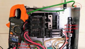
BUT IF I REMOVE THE N/G BOND IN THE TRAILER MAIN PANEL .... I ONLY HAVE 3.06VDC BETWEEN THE BATTERY (+) AND TRAILER FRAME.

What The ?? .... How I am seeing 47.4-49vdc between the Battery (+) and Trailer frame with the AC N/G bond, but ONLY 3.06vdc when I removed it. There is NO Connection to the trailer frame for Battery (+), Battery (-) or AC ground in main panel at all. Tested each and have NO continuity.

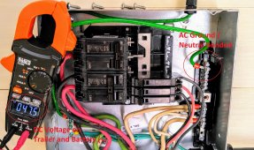
Here it is with the N/G removed - Very little DC voltage at between frame and battery (+)

AC Not Bonded.jpg

Here it is with the N/G bonded - over 47vdc between trailer frame and battery (+)
AC Bonded.jpg

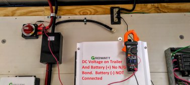
Here is the set up with the meter clamped to Battery (+) and trailer frame.
- It does not mater if I have the AC panel grounded or not (pictured AC grounded)
- I get DC voltage if N/G in bonded,
- And I get almost no voltage if N/G is NOT bonded

Trailer DC Voltage.jpg
 
Last edited:
So ... still wondering, Should I be bonding the Battery negative to the trailer frame along with the AC main panel ground in the trailer? From what I have tested here, I will probably NOT bond the AC N/G in the trailer panel. I can see where this might be causing the error code "Discharge Short Circuit Protection" that is causing the BMS's to totally disconnect with the hi surge of the 3 Ton AC kicks on.

Testing later today
 
So after removing the N/G bond in the Trailer main panel I was getting only 3.6vdc on the trailer frame connected to the battery (+). I also discovered 2 ground loops in the trailer that I fixed. Now only 1 ground point. I have the main panel ground. I DO NOT have the battery (-) negative grounded

I then connected everything to the house again. And as soon as I threw the breaker for the house, which enabled the whole house single point N/G bond .... I get 47.6vdc on the trailer frame when connected to the battery (+).

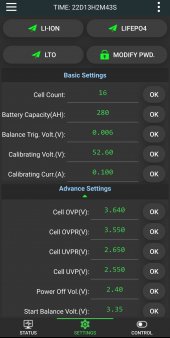
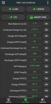
I also went into the bms and set the Discharge Short Circuit Protection to 2 second delay from a 1.5 second delay.

With 1500 watts of load running off grid, I powered up the 3 Ton and it started no problem or light blinks.

Still ... I do not understand why I am getting DC voltage between the Battery (+) and the trailer frame ONLY when there is a AC N/G bond?
 
Well it started the 3 Ton ... AND then it started the 1 Ton. and seemed to run fine for about 10 min. I have now set the whole house to normal loads and temps to see if it will start the 3 Ton again. The problem is not the Growatt 12 kW per say, it is the BMS. But it seems the BMS is responding to the voltage on the trailer frame. Was it shorting because of the Ground loops? Did it not error this time because I increased the short delay from 1.5 to 2 seconds? No idea here.

Any help appreciated

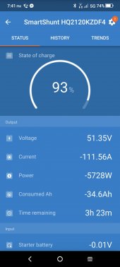
System with both 1 Ton and 3 Ton Running

Screenshot_2022-10-24-19-41-13-188.jpg
 
Only other tin I can think of is, does the Growatt have a Disconnect "QD"for disabling Output Neutral to chassis Ground bond inside the inverter, or possibly a relay to transfer ground when on "shore power". Victron etc has relays to switch pending on condition. I don't know about Growatt / MPP etc.

I use a Samlex EVO and all of that is built in including a smart ATS. (one of the reasons they are so pricey I guess) but they are designed for fixed residential (On or Off Grid), Mobil & Marine applications. Not many folks are up to spending $2000 on a 4Kw LF Inverter/Charger.
 
Yeah it does not. I have a Schneider Conext SW that also works flawlessly. Packed with software and features
 
If this is a factory wired trailer maybe they were sloppy and have neutral ground bonded by accident in plug and switch boxes. If you still have a converter there may be a frame bond there. Gas line may also be bonded and touching frame.
 
If this is a factory wired trailer maybe they were sloppy and have neutral ground bonded by accident in plug and switch boxes. If you still have a converter there may be a frame bond there. Gas line may also be bonded and touching frame.
Nah this was just an empty cargo trailer bought new for purpose. It is all plywood lined. I did the full install and have checked and rechecked. Not yet found a screw or wire that is Bonding with the frame. It's very odd.
 
I tore every AC connection out of the main panel in the trailer except for the AC in from the growatt.

Totally disconnect the battery and hunted for any continuity beeps between trailer frame and any + or - DC busbar connection across the system. If there's a DC battery cable shorted to the frame it's crazy well hidden.

Removed all grounds in the ac main panel. Not even the inverter case is grounded to the Frame. Nor is the ground busbar or main panel grounded to frame.

Started up BMSs. No battery positive turned on to inverter only DC negative to battery. Positive goes thru a boats switch inverter is off.

When the BMSs are live I get 3-4v dc when I meter between battery positive and trailer frame.

And with the inverter off and the ac ground busbar not connected to anything, if I bond with it to the ac neutral.... I get 48v dc between the trailer frame and the battery positive.

How is it even possible? There is no connection between the battery + or - to the frame. How can there be DC volts there
 
Back
Top