diy solar

diy solar

Growatt 3000 24v Reversed ground/Hot reading

ShockinglyAverage

New Member
Joined
Nov 10, 2020
Messages
35
So I've gone through the various threads that seem to relate to this problem and I still can't seem to fix it. When AC is passing through from the utility its fine, all my outlets test good. When I use the inverter to generate the AC my Paneltronics breaker panel would like up "reversed polarity." Everything would work fine but my tester would show "Rev Hot/Ground." After reading through the threads it seemed the fix was to run a jumper wire between the Neg IN and Neg OUT terminals on the growatt. I did that, and the "Reverse Polarity" light on the panel went off, however my tester is still showing the same "Rev Hot/Ground" reading and the test feature doesn't trip the GFCI outlets. Kind of at a loss here as I've checked and rechecked the wiring a dozen times and its all wired properly. Any ideas?
 
Sorta sounds like you do not have a proper ground. Perhaps a picture of your AIO's terminals and a wiring layout from your Main to your critical loads panels would help.
 
Sorta sounds like you do not have a proper ground. Perhaps a picture of your AIO's terminals and a wiring layout from your Main to your critical loads panels would help.
Please forgive my ignorance, AIO? Just for clarity this is in a van conversion, if that changes what you want to see.
 
Your Growatt is an All in one (AIO). Being as you are a Van setup (no ground other than chassis when not plugged into shore power) it is going to be a different scenario for establishing the proper connections.

Some of the RV and boat people would provide better assistance than I. It still would not hurt to post images of your unit"s wiring setup (Be cautious around hot circuits!)
 
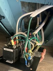
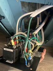
Here are the terminals for the growatt. This is after the jumper wire which is why you can (kind of) see two white wires going into each neutral terminal. The other picture is the Paneltronics breaker panel. Looks a mess I know but all the wires are correctly and securely attached. Also if it were a problem at the breaker panel I would assume I’d get the fault regardless of if it was from shore or battery as the panel is fed by the same wires regardless IMG_4106.jpegIMG_4107.jpeg
 
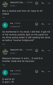
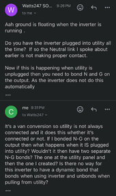
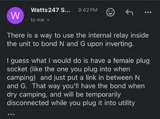
So this was my conversation with the seller watts247 (I don’t know if this is Ian specifically). Does this make any sense? I’m not even 100% sure what he’s suggesting in the last message. Does nobody in a mobile setup like van or rv really use this unit without some weird Jerry rigging?
 

Attachments

  • IMG_4108.jpeg
    IMG_4108.jpeg
    83.6 KB · Views: 7
  • IMG_4109.jpeg
    IMG_4109.jpeg
    116 KB · Views: 7
  • IMG_4110.jpeg
    IMG_4110.jpeg
    190.9 KB · Views: 7
So I've gone through the various threads that seem to relate to this problem and I still can't seem to fix it. When AC is passing through from the utility its fine, all my outlets test good. When I use the inverter to generate the AC my Paneltronics breaker panel would like up "reversed polarity." Everything would work fine but my tester would show "Rev Hot/Ground." After reading through the threads it seemed the fix was to run a jumper wire between the Neg IN and Neg OUT terminals on the growatt. I did that, and the "Reverse Polarity" light on the panel went off, however my tester is still showing the same "Rev Hot/Ground" reading and the test feature doesn't trip the GFCI outlets. Kind of at a loss here as I've checked and rechecked the wiring a dozen times and its all wired properly. Any ideas?
As described by Ian, you need to make a bonding outlet for your shore power cord.
Get a female cord end that matches your shore power cord.
Make only one connection in it. (A jumper between N and G)
Plug your shore power cord into it, whenever not plugged into shore power.
 
Ahh, I see. So which do you guys think would be a better option:
1) the plug mentioned above. Pro, you would have to remove it in order to plug into shore power so no chance of double bonding. Con, the only option for the 30amp twist lock on the back of my van would be a bulky 5” long female plug always sticking out of the back when not at a campsite.
2) Use a light switch inside the van to make a G-N bond when off shore power. Pro, leaves the outside looking clean, inconspicuous like originally designed and no plug to keep track of. Con, always the risk you forget to flip the switch when connecting to shore and end up with a double bond.
 
You can add a relay to do it automatically.
But the plug is simple and reliable.
 
Any threads or sources about the relay solution you can point me to? Appreciate all the help.
There is a diagram somewhere. But I don't remember where.
Basically, when there is power to the shore power a relay opens the N/G bond.
And when there is no power it closes.
Use a N.C. (Normally Closed) relay.
 
I have a GW 3K 24V inverter in my truck camper. These units would bond N-G internally under inverter power and open the bond under shore power. As far as I know, this has not changed.

I would not jumper N-G at the outlet or use a bonding plug without first determining if the unit bonds N-G.

Disconnect all input and output wires. Measure for continuity between N and G with the inverter turned off.

If continuity is present, the unit will bond N-G under inverter power. Do not add a bonding jumper or bonding plug.

What exactly is this mess? I assume it's a breaker panel. I'd get that cleaned up and I'd consult the manual for it. I would question why the EGC is on the first terminal because it looks off to me but I don't have the model number. For the 6 panel shown here, it is six breakers in a row and you have an EGC mounted to the first breaker. An EGC is never fused or on a circuit breaker.


1708368442769.png
 
If these units work as perfectly as you claim then why are there literally dozens of threads and YouTube videos about how to deal with the problem I laid out? Is my breaker panel OCD compliant? No. But it is perfectly safe and I have consulted with Paneltronics and can confirm it is wired properly. Additionally, if the problem was at the panel then it would show up regardless of whether using shore or inverter power as its all the same wiring at that pint in the circuit.
 
If these units work as perfectly as you claim then why are there literally dozens of threads and YouTube videos about how to deal with the problem I laid out? Is my breaker panel OCD compliant? No. But it is perfectly safe and I have consulted with Paneltronics and can confirm it is wired properly. Additionally, if the problem was at the panel then it would show up regardless of whether using shore or inverter power as its all the same wiring at that pint in the circuit.
Did you do as I instructed? It has to be determined if N-G is bonded in the inverter under inverter power and there is only one way to find out. You have to test with all wires disconnected on AC input and output. The older versions bonded N-G dynamically under inverter power but later models may have had internal changes that are not documented. You can't go by what some clown on the web tells you, you have to test it yourself. You are looking for the easy answer without performing actual testing.

If the inverter bonds N-G under inverter power and you add another N-G bond by jumpering or a bonding plug, objectionable current will flow on G, thus you will get what you describe as you have a parallel path on G. While Ian does have some good points, he also has some practices I'd call questionable and can lead to inverter damage, failure to clear a ground fault and even severe shock to yourself.

As you did not give the model of the Paneltronics panel, we all get to guess on what you have. The more information provided certainly helps others know what exactly you have. I had to do some more digging to find what appears to be your AC panel. The correct diagram is this one. https://www.paneltronics.com/docs/wiring/2305.pdf?v=20240219042206 Looking at that diagram, there is a N-G bond on that panel at the top where G attaches to the panel. The terminal below it is N. There is a jumper between N and G and this is why you are seeing your problem. No, this is not wired correctly. The bond between N and G at that point needs to be removed. You have a parallel path and I'm quite certain when you actually test the inverter as I described in this post, you will find that indeed this inverter is bonding N-G under inverter power.

You can thank me later, I'm just some guy on the internet that owns one of these units and how it operates but don't know squat according to your response.
 
It has to be determined if N-G is bonded in the inverter under inverter power
It's already been confirmed that the ground is floating in battery mode.
By the voltage readings in the pictures of the text conversation.
 
It's already been confirmed that the ground is floating in battery mode.
By the voltage readings in the pictures of the text conversation.
3 N-G bonds are present with the N-G output jumper in place, the N-G bond in the panel and N-G bond from the inverter.

G to L should be 120V. It is not, there is power on G as shown by the 75V reading of G to L. That means there is 45V present on G. It has to come from somewhere.

This situation is dangerous.

The N-G bond for the inverter needs to be checked first and foremost as I described. Filter Guy, myself and others went thru lengthy discussion on these inverters when the inverters were first introduced. In that process, we learned the proper way to check these for dynamic bonding.

The N-G bond in the panel needs to be removed if the inverter does dynamic bonding.

Shore power will provide N-G bond and the inverter will disconnect N-G bond if it is dynamic.
 
3 N-G bonds are present with the N-G output jumper in place, the N-G bond in the panel and N-G bond from the inverter.
I'm not sure what you are referring to. There isn't a N/G output jumper.
G to L should be 120V.
Correct
It is not,
Because there's no bond.
there is power on G as shown by the 75V reading of G to L.
No, this shows that it is floating.
That means there is 45V present on G. It has to come from somewhere.
No, this also shows that it's floating.
These readings are just potential voltage. They can only be seen on a digital tester. They can't carry current.

This situation is dangerous.
I agree.
Because there's no ground when operating on battery.
The N-G bond for the inverter needs to be checked first and foremost
It was.
Filter Guy, myself and others went thru lengthy discussion on these inverters when the inverters were first introduced.
I was there.
The N-G bond in the panel needs to be removed if the inverter does dynamic bonding.
There isn't one, and it doesn't.
Shore power will provide N-G bond and the inverter will disconnect N-G bond if it is dynamic.
Correct, and it's not.
 
Until the inverter is tested with all wires disconnected from AC input and AC output for continuity between N-G with the inverter off, there is no clear answer. Later units had a setting (#24) for bonding purposes using an external bonding relay, however we do not know when his model was produced. Ian could have had inventory before the addition of that setting.

There is 45V on G that should not be there. G to L voltage should be within 3V of 120V. Where that path is remains to be determined.
 
Last edited:
Back
Top