mint
New Member
Hello everyone,
Looking for some guidance/assistance/tips or just anything that might help me.
(Note, I'm not an electrician in anyway shape or form and for anything that requires a qualified electrician will be done so by said electrician and not myself but my aim is to learn and do as much DIY as possible).
I'm currently looking at a Growatt SPH 6000 (specifically for the output power to AC of 6KW as this caters to my peak loads) with x1 or x2 7Kwh Lifepo4 batteries to go alongside, now I've spent a solid week looking at the wiring and diagrams of how this all works and from what I've read this is somewhat inverter dependent in terms of wiring.
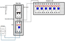
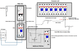
Looking at the literature for the SPH 6000, I've (crudely) drawn the current wiring diagram and what I believe will be the new wiring diagram and wanted to run this by you kind folks for some advice and mainly to make sure I don't look like a donut showing this to an electrician!
Current Circuit

New Circuit

Now onto the actual Q's
TIA!
** Mods feel free to move this since I've just realised I posted this in General **
Looking for some guidance/assistance/tips or just anything that might help me.
(Note, I'm not an electrician in anyway shape or form and for anything that requires a qualified electrician will be done so by said electrician and not myself but my aim is to learn and do as much DIY as possible).
I'm currently looking at a Growatt SPH 6000 (specifically for the output power to AC of 6KW as this caters to my peak loads) with x1 or x2 7Kwh Lifepo4 batteries to go alongside, now I've spent a solid week looking at the wiring and diagrams of how this all works and from what I've read this is somewhat inverter dependent in terms of wiring.
Looking at the literature for the SPH 6000, I've (crudely) drawn the current wiring diagram and what I believe will be the new wiring diagram and wanted to run this by you kind folks for some advice and mainly to make sure I don't look like a donut showing this to an electrician!
Current Circuit

New Circuit

Now onto the actual Q's
- Based on the above diagrams (in principle) am I on the correct understanding as to how the wiring works?
- The line running to the inverter is going to be approx 15m and as my long term aim is to be able to have 12KW internally (battery + solar), how much should I overprovision the cable by? Right now I'm looking at BS6004 6.0mm² (clipped externally)
- The EPS wiring according to https://midsummerwholesale.co.uk/pdfs/044.0054307-sph3-6k.pdf (page 15 diagram C) it appears what I'm aiming for can be done but I'm not sure if this would be okay to setup in the UK e.g. If this has any bearing over G99/G98
- Would it be possible to have the EPS output as a secondary to grid in the consumer unit and have an automatic or manual switchover so's that the inverter would effectively power the CU via EPS (I know this is limited to 3KW but I'd just keep the rings off that would take me over the limit or if x2 inverters in parralel then this would increase to 6KW max)
TIA!
** Mods feel free to move this since I've just realised I posted this in General **
Last edited:


