diy solar

diy solar

Growatts in Parallel - Do I need to connect AC Output GNDs together?

Zero_PD

New Member
Joined
May 20, 2022
Messages
27
Location
SF Bay Area
So I'm wiring up two Growatt 3k's in parallel. In the manual it shows the Line and Neutrals tied together in parallel, and your load (in my case a couple outlet receptacles) will tie to those now-paralleled AC outputs.

  1. What about ground? Does the Ground AC output need to be tied together between the inverters? If not, which ground should I tie my outlet receptacles to?
  2. Will there be an issue if I do tie the grounds together as well, along with the line and the neutral, and then tie all three to my outlet receptacles? Currently, I've tied GND, Line, and Neutral together (see pic).
  3. When I was testing connections I found that Neutral and Gnd appear to already be tied together. Does this mean I should remove the Ground bar? And lastly, does this mean I only need to wire Neutral and Line to my outlet receptacles? Or can the GND connection to my outlet receptacle come from the Neutral distribution bar as well?

Thanks!
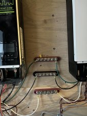

parallel AC out.jpeg


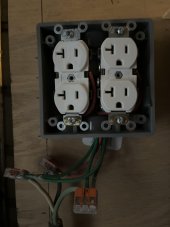
receptacle.jpeg
 
I think if inverter outputs tie together and feed an outlet or breaker panel, then grounds should tie together too.
Whatever path current takes, if there is a fault to ground, current should be able to travel in a ground wire in same cable or conduit as the power.
If power can split through two parallel inverters, fault current in ground should be able to follow same split.

Those wires seem a bit small for the current I think the inverter can put out. But maybe not - 3kW? What amperage? what wire gauge?

Would rather see all individual wires in electrical boxes or conduit, not separated and open.

We bond neutral to ground at a single point. At first disconnect, I think code says. For me that is grid-fed utility panel. Maybe yours is inside the inverter (should only be in one not the other), or isolated in both inverters and bonded in a breaker panel. A breaker panel ought to be part of your system.
 
Those wires seem a bit small for the current I think the inverter can put out. But maybe not - 3kW? What amperage? what wire gauge?

The wires are 12 gauge. It is marginally undersized for the 3kW maximum output, and I may rewire with 10 gauge, but considering the short distance and the max 30A output (I never pulled more than 20 when my system was previously running) I can likely get away with it.

Would rather see all individual wires in electrical boxes or conduit, not separated and open.

I agree it could use some cleanup. I've ordered some conduit to clean it up a bit.

Would rather see all individual wires in electrical boxes or conduit, not separated and open.

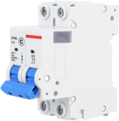
By electrical box, do you mean a circuit breaker box? I'm embarassed to say I'm not entirely sure how they work. I will have circuit breakers in between these three bus bars and my outlet receptacles which will be mounted above them. They will be individual breakers that look like this though.

1691859034011.png

There are only three outlets. It sounds like I could get a small circuit breaker panel and wire my AC outlet in parallel to the circuit breaker panel and then wire my outlets to that?


Just to bring it all back to the start - it seems like there's nothing (electrically) incorrect with how I have it now, and I can wire an outlet receptacle to the GND, L, and N bus bars I've wired up without issue?
 
DIN rail enclosure would be the way to mount that type of breaker.
Mostly I use Square-D QO breakers that plug on a bus in a box. I have a couple DIN parts, relays and magnetic-hydraulic breakers that better meet system needs.

Regarding N and G, a diagram tracing out all connections would be useful. There should be a ground rod somewhere. GFCI breakers or outlets are good if any wet locations.

I don't like exposed 120Vrms "L" busbar at all! A tool should be required before a finger can reach hazardous voltages.
 
Back
Top