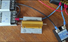
tl;dr: A solar charge controller is expecting a solar panel as its power source. Using anything else - such as this constant voltage power supply - is simply wrong. You can make it work, if you have absolutely no other option, by using a 3.0ohm, 105W resistor in series with the solar charge controller, and here's 1) the reason for the issue you're having, 2) the math behind the 3ohm resistor recommendation, and 3) the correct solution for the system you appear to be building:
1) What is happening?
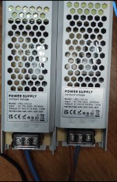
PWM solar charge controllers maximize current as long as the input voltage is above the battery voltage (plus some amount of minimum voltage drop internal to the PWM switches used). You have constant voltage power supplies, put in series they supply 48v at 6.3A, or 300W. The PWM charge controller is a 30A at 24v, or 720W. 30A > 6.3A, and when the charge controller tries to pull 30A, your power supplies recognize a fault condition, and shut down to avoid damaging themselves.
Putting a resistance in series reduces the voltage at the charge controller - as it ramps up the current the voltage drop due to the resistor increases, and eventually the voltage at the charge controller is just above the battery voltage, and it stops trying to pull more current.
In other words, you're making your constant voltage power supply look more like a solar panel - which is what these PWM charge controllers are expecting. As the current goes up, the voltage goes down. The total power output varies. Here's a chart of your situation with the resistor in place:

The current, along the X axis, determines the voltage drop across the 15 ohm resistor (blue). V = I * R (Ohm's law) indicates that, for instance, at 2A of current through the 15 ohm resistor, the resistor will have 30V across it. That leaves 48-30=18V for your charge controller. Except your battery voltage will be above that, so the PWM charge controller will never pull that much current. It will pull enough current to bring the input voltage down to the battery voltage. Once the input voltage (orange) equals the battery voltage, or just above it, it will not pull more current.
This means your charge controller will pull under 1.5A using this setup, which means it will charge the batteries at 1.5A * 25.5V = 36W. The power resistor will have a 22.5V drop, and at 1.5A it will be generating ~34W. So of the 300W of power available at the power supply, 36W will go into the batteries, and 34W into heating the air.
2) Maximizing power transfer by changing only the resistor
If you want to maximize the power going into the PWM controller ONLY by changing the resistor: The maximum current the power supply can give is 6.3A. Let's leave a little overhead to avoid shutdown, and consume 6A. At full charge, the batteries will be around 28.8V. Let's assume the PWM charge controller is very efficient, and has less than a 0.2V drop between input and output.
This means the maximum power transfer occurs when 6A is pulled with 28.8V+0.2V=30V at the input of the charge controller. With a 48V power supply, the resistor needs to drop 48V-30V = 18V. 18V at 6A the resistance needed is 18V/6A=3ohm. The resistor will be generating heat, with a 18V drop and 6A it'll generate 18V * 6A = 108W.
You'll need a 108W or better 3ohm resister, and you'll need to add a cooling fan to prevent the resistor from overheating - it needs to remain under 40C. The charge controller will be converting 30V * 6A = 180W into the batteries with 28.8A * 6A = 173W actually going into the batteries.
This means you'll consume 48V * 6A 288W, with only 173W going into the batteries, and the rest being converted to heat. Given the power supplies are only 86% efficient, you'll be drawing about 335W from the mains. Your total conversion efficiency, therefore, is 52%.
Just to re-iterate, as it's a safety concern, the resistor will go past 200C before it fails it you do not actively cool it. It will generate 100W+ of heat that you MUST move away from the resistor. If you don't,
You're Gonna Have A Bad Day™.
3) A better solution
The real question, though, is WHY? What is the point of using two converters, from AC to 48VDC, then from that to your battery's 24VDC? Even if you chose two very efficient converters, you're still spending more money on those converters, and they're still wasting more of the energy than one converter would use.
A 24V LiFePO4 charger (AC directly to battery) is between $60 and $200 (
https://www.google.com/search?q=24v+lifepo4+charger ), which is probably less than the cost of your two power supplies and the pwm charge controller. Even one of the cheap 24V 10A chargers will push 240W into your batteries with under 36W lost in conversion - an 85% charging efficiency, compared to 52% efficiency of the hack you're trying to make work.
Assuming you have a 50AH battery bank, your 48v-->resistor-->PWM-->battery setup will charge in just over 8 hours, putting 1.4kWH into the batteries, consuming 2.8kWH in the process. With a 10A charger directly into the batteries, though, it'll take 5 hours, putting 1.4kWH into the batteries, consuming 1.6kWH in the process.
The new power resistor, cooling fan, and appropriate mounting/airflow/fire safety enclosure is going to cost $45+, so there's even less reason to continue to pursue this hack.
Solar charge controllers expect and should be used with solar panels as the input. Using any other power source - whether another power supply, battery, alternator, generator, etc - is almost always a bad idea.
Find and use a charge controller with the input that matches your power source.


 IMG_20230113_233701.jpg337.8 KB · Views: 31
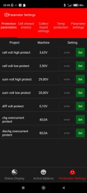 Screenshot_2023-01-13-23-45-21-447_com.inuker.bluetooth.daliy.jpg122.5 KB · Views: 30
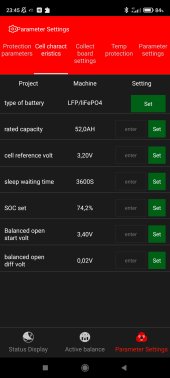 Screenshot_2023-01-13-23-45-24-898_com.inuker.bluetooth.daliy.jpg119.1 KB · Views: 35
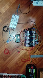 IMG_20230113_223628.jpg185.5 KB · Views: 37
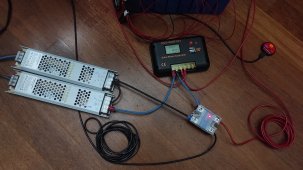 IMG_20230113_222412.jpg394.3 KB · Views: 37
 IMG_20230113_222422.jpg295.7 KB · Views: 32
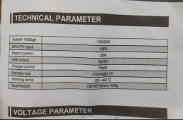 IMG_20230113_234247.jpg260.3 KB · Views: 30