diy solar

diy solar

Hello from Atlanta

smbranch62

Starting a new Jerney
Joined
Nov 11, 2020
Messages
10
Location
Atlanta GA
Hello everyone, coming to you from Atlanta Ga. I'm in the planning stages of a van build out. I plan on building out a ProMaster 2500. I also plan on building my own LifePo4. I have begun to purchase all of the pieces associated with the build. I'm currently waiting for my cells to arrive from China (Alibaba), should be here by the end of this month. I have been reading this forum for a little while now and I really appreciate how people are really helpful and knowledgeable. Looking forward to contributing to the forum.
 
Welcome to the forums. What voltage for the battery and what size cells are you using?
 
Welcome to the forums. What voltage for the battery and what size cells are you using?
Hey DThames, it will be a 12v battery pack and I'm will be using the Lifepo4 3.2V 271Ah.

My BMS - 4S 12V Lifepo4 Battery Smart BMS With Bluetooth Function UART And RS485 Communication With 60A To 120A Constant Current​

 
Last edited:
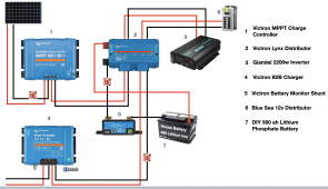
I have a quick question... I plan on using the Victron Lynx Distributor, is it best practice to connect the Battery charger and the B2B charger to it? or should I have a buss bar between the shunt and Lynx Distributor?
 

Attachments

  • Screen Shot 2021-04-24 at 9.18.01 PM.png
    Screen Shot 2021-04-24 at 9.18.01 PM.png
    863.5 KB · Views: 8
A busbar is most common if you plan on having multiple circuits off it. If you're following the photo, then that need is met by the Bluesea distributor and probably safer as the 12V sources will be fused.

What seems to be missing from that picture is a fuse between 2 and 7....possibly embedded in component 2?
Update: Yes...embedded in the Lynx:
A modular DC bus bar, with locations for four DC fuses. It will monitor the status of each fuse, and indicate its condition with a LED on the front.
 
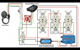
Hey guys thanks for the input, it's really appreciated.... Next is my Shore Power layout. Please give me some constructive criticism. I really want to know that i'm on the right track. Thanks
 

Attachments

  • Van Shore Power.png
    Van Shore Power.png
    786.8 KB · Views: 5
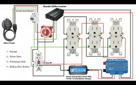
If you make your first outlet a GFCI, all the other outlets will be protected.
Assume the Giandel has a 15 amp circuit breaker (or are all the receptacles 20 amps)?
Assuming that from the 1/2 switch the bottom red line in the common and the switch switches between the left/right red lines... then you might have a problem that the inverter is providing power to charge the batteries that the inverter is draining; that is you might want to hook it to the 1-side of the switch only.
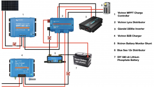
Thanks for the input Svetz. My thought was that when switch 2 is active, that the inverter will perform as normal, it will be getting power from the house battery. My goal was not to use the Inverter while connected to Shore Power, while having the ability to charge the house battery and usage of the outlets.
 

Attachments

  • Van Electrical Layout.png
    Van Electrical Layout.png
    857.8 KB · Views: 4
  • Van Shore Power.png
    Van Shore Power.png
    817.3 KB · Views: 3
Back
Top