Thingol
New Member
- Joined
- Dec 8, 2020
- Messages
- 49
I recently purchased this JBD BMS here at the IC GOGOGO Aliex store and I am currently locked in a refund tussle with the seller. Seller is unsurprisingly unwilling to replace or refund. I would like some assistance diagnosing and fixing the problem to see whether repair would be the best solution. Here is what's going on:
BMS got delivered fully functional, no signs of damage or wear, we hooked it up to our 48V bank (after testing correct balance lead connection) and everything worked without issues. Two weeks later, the BMS voltage sensing was completely wrong e.g., reading 2.5V for a cell whose actual voltage (measured on the connector and at cell) was 3.3V. The BMS has never run more than 80 amps, and is rated 200 amp. We took it out and:
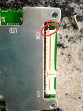
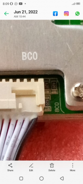
1) The 3 resistors on BC0 side were charred and one was even split midwise. All 6 resistors on BC0 side and on BC21 side are labelled 620, meaning each one is 62 ohms-we could read this from older photoes from before the ones on BC0 burned out.
Current BMS photos showing burned out BC0 resistors:


Photos from earlier showing resistor ratings for both ends:


2) Now, on the BC21 side (positive end), the resistors are not burned out, but they all measure 20 ohm-against the expected 62 ohm:

My best guess here as an electonics noob is that the unit was built with low quality components and the BMS is not up to scratch (expecially having tested the leads voltages to ensure correct arrangement before plugging in). Other than that, I cannot tell why the BC0 resistors (-ve end) smoked, or why the BC21 resistors (+ve end) are reading 20 ohms instead of 62 ohms. Any help / insights as to what went wrong and whether we should simply replace all the resistors would be greatly appreciated!! @upnorthandpersonal
BMS got delivered fully functional, no signs of damage or wear, we hooked it up to our 48V bank (after testing correct balance lead connection) and everything worked without issues. Two weeks later, the BMS voltage sensing was completely wrong e.g., reading 2.5V for a cell whose actual voltage (measured on the connector and at cell) was 3.3V. The BMS has never run more than 80 amps, and is rated 200 amp. We took it out and:
1) The 3 resistors on BC0 side were charred and one was even split midwise. All 6 resistors on BC0 side and on BC21 side are labelled 620, meaning each one is 62 ohms-we could read this from older photoes from before the ones on BC0 burned out.
Current BMS photos showing burned out BC0 resistors:
Photos from earlier showing resistor ratings for both ends:
2) Now, on the BC21 side (positive end), the resistors are not burned out, but they all measure 20 ohm-against the expected 62 ohm:
My best guess here as an electonics noob is that the unit was built with low quality components and the BMS is not up to scratch (expecially having tested the leads voltages to ensure correct arrangement before plugging in). Other than that, I cannot tell why the BC0 resistors (-ve end) smoked, or why the BC21 resistors (+ve end) are reading 20 ohms instead of 62 ohms. Any help / insights as to what went wrong and whether we should simply replace all the resistors would be greatly appreciated!! @upnorthandpersonal