diy solar

diy solar

[Help] DIY Router UPS Backup

existinginthespace

New Member
Joined
Dec 25, 2020
Messages
5
The other day I had a blackout, every time it happens, my router settings reset.
I was first planning on buying an APC UPS power strip but was surprised that they use lead-acid batteries in them, are inefficient, and fail often.
So instead I want to try and build my own Lithium-Ion Router UPS.

I was inspired by this youtube video

My router specs are
19 volts
3.16 amps


While I have watched almost every video by Will Prowse, I haven't built my future solar system yet.
So my actual hands-on experience with electronics is limited to simple Arduino projects.

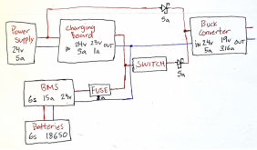
My plan is the build a 24v battery bank.
Use a 24v power supply and use a 24v charging board.
I will then use a buck converter to step-down the volts and amps to my router settings.

I'm looking for feedback on if the schematic looks correct.
Also, please correct any misconceptions I might have based on this schematic.

Do you need to regulate amps out on the charging board and buck converter or does the system only draw what it needs?

Do u need a step down charging board?

Did I place the Schottky diodes in the right location? Are they the right amps?

Is the fuse needed? Is it the right size?

Thank you for the feedback and corrections.

If there's any quality hardware you recommend, feel free to leave me a link

Here's my schematic
Screenshot from 2020-12-24 17-19-22.png
 
Last edited:
What type of router (brand and model) is it? Where did you get the 19v, 3.16 amps from? Does it have a wall power adapter that plugs into a DC input on the router? If so is the DC input marked. I would expect 12v. 19v is odd.

A 12v pack fro a 12v system is a much simpler approach. You just have to have one charger board.
 
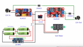
Diodes, notice he is using 12v in and 12v out. If the input is a tiny bit higher than the output of the XL6090 board, the input power source will cause the diode on the XL6090 to be reverse biased and the power will come from the input supply. When the input supply is going, the XL6090 voltage will reverse bias the other diode (top of image) and the power will come from the battery, through the XL6090.

In your example you are not running off of the input, but I see you are trying to power the Buck Converter from two sources and yes I think you have the diodes in correctly. One thing I am not sure about is if your charging board is any draw on the battery when it is not powered. You might need a diode there. I have noticed in my applications that the battery can drive back and keep a light on the charging board when the input power is lost. So you might want to see exactly what is going on in the power out state with the battery backfeed.


Capture.PNG
 
Thank you for the feedback, I really appreciate it!

My router is a Netgear Nighthawk X6S.
It's a beefy looking router.

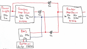
I've drawn an updated schematic and removed the fuse and switch for the time being.

Some questions, when the power supply is on, is the router step-down drawing current from the batteries?
If the power supply goes down (blackout). The batteries automatically kick in?

Does the battery bank try to give off 24v 15a to the router step-down?
Do I need to limit the amount of current that goes from the batteries to the router step-down?

Updated schematic, version 1.2
Screenshot from 2020-12-27 11-29-13.png

XL4016 Step Down Buck Converter
300W XL4016 DC-DC Max 9A Step Down Buck Converter 5-40V To 1.2-35V Adjustable Power Supply Module LED Driver
 
Last edited:
"Some questions, when the power supply is on, is the router step-down drawing current from the batteries?" Will draw (mostly) from the one with the highest voltage.

"If the power supply goes down (blackout). The batteries automatically kick in?" Will draw from the one with the highest voltage.


"Does the battery bank try to give off 24v 15a to the router step-down?" No. Up to 15amps is available, if the load demands that much. The router will likely need only 1 amp or so.

"Do I need to limit the amount of current that goes from the batteries to the router step-down?" No, the BMS will limit to 15a. A 6a BMS would work just as well, maybe a better fit.
 
Thanks for the help. I really appreciate it!. I'm going to start ordering parts and hopefully have a working prototype by end of January.
 
Please let up know how this went.
I might try something like this.
Hey there, I'm still waiting for a few more items to arrive from Aliexpress.

I found some other youtube videos that I plan to use for reference.

Here are some of the resources from those videos.
12v 19v build
part 1
part 2
part 3

19v & 12v UPS schematic

As an update on my future plans. I plan to make my battery bank and UPS backup as separate components.

Like that, I can freely use the battery bank for other projects and reconnect it back to my UPS after.

My UPS will not be able to charge the battery bank, this is to improve safety. I will handle charging my battery bank manually.

My UPS component schematic will look similar to the youtube videos referenced in this post.

My UPS will have two power source inputs; 19v for my router and 12v for my modem.

My UPS will also have an input for the battery bank.

My battery bank will be 6s2p for a 22.2v nominal voltage battery.

My UPS will have two step-down converters to drop the voltage down to 19v for the router and 12v for the modem using a relay to switch between using the power source input or the battery bank input.

That's the current plan. Let me know if you have any more questions
 
Wow, thanks!
There is a lot of great information here.

They should rename Aliexpress to Aliponeyexpress. :)
My first project will be sourced locally. the next one can be from Aliexpress. Not ready to wait 2 months for parts.
 
Back
Top