diy solar

diy solar

Help in understanding new DIY solar setup - voltage drop from panels to SCC

OP: "even if the voltage from all my panels is around 114V...it doesn't directly mean you're getting top amps as advertised on the panel"
The load PULLS the current from the panel as it needed.
 
As it is available from solar production in the cells. It can only pull what is available from the solar cells. The amount of solar energy being produced.
I'm sure we're saying the same thing. :unsure:

I think OP is a victim of northern climes and lack of sun. It was cloudy today in so-cal so we're sad. Usually it's sunny every day. ?
 
Wow, you all are amazing with your replies and knowledge. @12VoltInstalls is right ..to say I'm green on understanding and applying this solar stuff is only just beginning. @Bud Martin , @12VoltInstalls , @Browneye ,@Cal thank you for the extra information and learning - so I'm getting some info into my brain and slowly getting this through trial/error/discussion .

Going to reset the SCC back to factory and tweak... Epever has such strict rules on order of things... probably to prevent people like me to damage the unit. I'll try any and all suggestions.

I loved the comment that I didn't get ripped off ? I actually had that thought cross my mind along with when I used my multimeter the wrong way and blew its fuse and some components within it?.

You all have been great to chat with. I never knew being on a forum could be so rewarding!
I'll report back what I've done and the results soon. Thanks again ??
 
thank you for the extra information and learning
Well you are welcome but just to be clear I know what I know but there’s EEs and other intelligent people who are way beyond me. I certainly don’t know much myself.
 
Well you are welcome but just to be clear I know what I know but there’s EEs and other intelligent people who are way beyond me. I certainly don’t know much myself.
I understand. I went into this knowing that we can't be everything...but as this community has shown, we can do great things when we share knowledge. Thank you.

I love when I've been struggling with a concept or project coming through the other side just a bit more aware and knowledgeable to help the next person ? . I'm honoured to receive the help.
 
Hi everyone, I've been busy doing life with other competing priorities. Here's my current situation:

1. Reset the Tracer 5415 back to factory...no change in how it handled the incoming voltage. It still pulled only ~27 volts
2. I tweaked the settings on the SCC back to what I had but did notice that the boost reconnect was at 24.8... could that be why my scc decided to take in the full voltage of ~114 volts after the battery reported charge of 24.8 volts?
3. When it was bringing in that high voltage, I noticed that the battery bank hovered around 26.6 volts...it never went higher than that. I thought the SOK specs are that a full charge should be above 27 volts at least...like 28.4(~14.2 volts each battery).
4. I saw that there was a 24 volt charger from victron... So I bought the IP67 24 volt charger with 2 or 5 amp charging.
4a. I probably still don't get amps or batteries but I drained the battery bank to 20 volts (even though my shunt monitor and the SCC reported 8 volts! I did verify with my multimeter that each battery was about 10.5 volts) last night to test the charger.
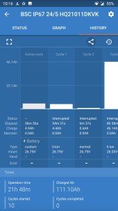
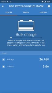
4b. I have been running the charger using the LION settings at 5amps for around 10 hours and it never reports the state going from bulk to absorption. I included a pic... So I've read that you can charge at much higher amps but this unit doesn't go that high... Did I make another mistake buying the charger? Or can I tweak it's settings properly?
4c. Is it possible my SOK batteries have tripped into some state of protection? How could I test that? I bought the Sok for the main reason that the parts were replaceable and Sok had a good reputation of support.
 

Attachments

  • Screenshot_20220101-101630.jpg
    Screenshot_20220101-101630.jpg
    172.8 KB · Views: 3
  • Screenshot_20220101-101612.jpg
    Screenshot_20220101-101612.jpg
    136.8 KB · Views: 3
10.5V for a LiFePO₄ is about 1% or 2% SOC. Don't do that. The SOK specs state the recommended low voltage disconnect (LVD) be 11.2V. The BMS LVD is 10.4V. You have 25.6V 206Ah. Charging 206Ah at 5A will take 41.2 hours. At 10 hours you were barely started. Be patient.
 
10.5V for a LiFePO₄ is about 1% or 2% SOC. Don't do that. The SOK specs state the recommended low voltage disconnect (LVD) be 11.2V. The BMS LVD is 10.4V. You have 25.6V 206Ah. Charging 206Ah at 5A will take 41.2 hours. At 10 hours you were barely started. Be patient.
Oh boy...I feel like a goof! Thank you @rmaddy ... One major flaw of mine, quite seriously, is my lack of patience. I needed to be reminded of that. Ok, more questions:

1. I should've been watching the inverter as it beeped when it was in trouble of providing more power than the batteries could supply. I read this inverter beeps at 19 volts. In the future, should I watch it more closely and shut it off at 20 volts?

2. Speaking of impatience, I turned on my system for the first time without fully charging the bank... I was too impatient to wait for my charger to come in?... I'm always concerned that I've ruined a component (yes, I'm a a worrier too?)
Is it possible I've ruined some cells in the batteries?

3. Yesterday when testing the output I had some LED grow lights running to see how long they'd run for on the bank. The lights specs say each light uses 42 watts. I had 8 connected with a couple 1 amp devices ... So, the total watts being used would have been close to (42*8=336 watts plus 2 amps(according to the labels) for the extra devices I had). Does that mean that the amount of amps used by lights was 2.8amps (336 watts ÷ 120volts) for a grand total of ~4.8 amps? I ran those things for around 7 hours until the beeping started. If that's true then with a 206ah lifepo bank how long can I expect to run effectively? I heard you shouldn't use 100% of battery. If I used 75% of 206ah it's 154.5ah... so shouldn't I have been able to keep that running for at least 30 hours modestly? Why did it drain so quickly?

I honestly need a DC clamp to do all this troubleshooting... I honestly never came across all the equipment I'd need to maintain this but it's worth it.

Thanks for the lessons...I honestly appreciate your time and help.
 
I should've been watching the inverter as it beeped when it was in trouble of providing more power than the batteries could supply. I read this inverter beeps at 19 volts. In the future, should I watch it more closely and shut it off at 20 volts?
I would not let the batteries get below 23V, ever. They will be bulk charged at about 28.4V - 29.2V. They will be floated at about 27.2V. A 24V LiFePO₄ will settle, after charging with no load, at about 27V. Going down to even 24V is over 90% usage. You might want to see the chart in the following post:


I turned on my system for the first time without fully charging the bank... I was too impatient to wait for my charger to come in?... I'm always concerned that I've ruined a component (yes, I'm a a worrier too?)
Is it possible I've ruined some cells in the batteries?
The BMS will shutdown the battery before any cells get ruined. That's its job. You should be fine.

But when you want to put two LiFePO₄ batteries in series you must first get both to the exact same SOC before you connect them in series. On the SOK website for the 12V 206Ah battery it states:

Notice for connect in series: If you need connect batteries in series, they should be at the same state-of-charge (SOC)before they are connected.

What you need is a 12V LiFePO₄ friendly battery charger. Fully charge both batteries, one at a time, with the 12V charger. Then wire the two batteries in parallel (yes parallel, not series, still at 12V). Hook up the 12V charger so the positive lead is on one battery's positive post and the negative is on the other battery's negative post. Do one more full charge cycle. Disconnect the charger leads but leave the two batteries connected in parallel for a few hours and let them settle together. Then disconnect the parallel wires and then you can finally connect them in series in your 24V system.

Failure to do those important steps will result in unbalanced batteries and over time you will have poor performance from the batteries.

Once properly charged initially as I described and together in series in your 24V system, using the 24V charger is fine. It's no different than charging via the solar charge controller. But you do not want to use the 24V charger to do the initial charge of the batteries. That must be done with a 12V charger as I described.

Yesterday when testing the output I had some LED grow lights running to see how long they'd run for on the bank.
Stop. Disconnect your batteries and get them fully charged correctly before you make any more attempt to apply a load to them. They are too expensive to abuse needlessly from the start.
 
Thanks for all that info, @rmaddy ☺️ super helpful.

Well I've only done the load draw twice so maybe dodged that arrow! I will do exactly as you say and get a lifepo friendly charger .. and follow your steps.
I would not let the batteries get below 23V, ever. They will be bulk charged at about 28.4V - 29.2V.
I didn't know that at all! Thank you!

So I need more patience, huh? LoL... I'll get step 1 done first and read that post you listed before I bother you all with my mania. Thanks again and I'll report back soon.

Oh...and Happy New Year to you all!!!!
 
Could be related to available sun, or shade. Could be screwy firmware in Epever, which some people have had trouble with.

But what about the panels themselves? New or used?
Defective panels can give full Voc and Isc, but poor Vmp & Imp.

At least one of your SCC screen images showed reasonable values, things are at least halfway OK.

When I noticed low current from one PV string in parallel with another, I used a space heater as resistive load to test individual panels.

 
But what about the panels themselves? New or used?
Defective panels can give full Voc and Isc, but poor Vmp & Imp.
The panels were 'new' in the sense I purchased them from a solar installer company who had only 3 of my panels for a job that got cancelled. However, I didn't notice a couple scratches on the glass of a couple of them when I picked them up - I was so excited to start my project and had rosy goggles on at the time ?. One of the scratches being about 18 inches long...and some micro scratches. At the time, I was so happy to get a 'steal of a deal' as they let me have them for around $130 CAD each... I didn't know what to look for in terms of damage and possible low quality. I will have to look up what Isc, Vmp, and Imp are (I have seen them and researched them but it's been a while since so I'll have to refresh) - then I'll have to learn how to test for that. I don't want to seem like the guy that just asks without doing their own work of learning about it all unless I hit a snag.

Now firmware for the Epever is something I didn't think about. I'll definitely look into that. I'm a big fan of updating those types of things but totally forgot about that. Thank you @Hedges !
 
I'm a big fan of installing something once and never changing software/firmware so it continues to operate the same forever. Sadly, with Windows 10 those days are gone, but even before (with Windows 7), I found my CAD behaved differently after a while. Affected by automatic OS updates, I think.

I've read here of people having to reset an Epever to get it back to producing what it should. But I haven't read that updates were available which fixed anything.

At a time when your battery is low enough to accept the current and not reach full charge for a while, you could try connecting first a single panel directly to it, then each individually, then move up to all in parallel. Looks like battery voltage would be just slightly below Vmp, so should give pretty good charging. Of course, you would need a way to measure the current (if presently relying on SCC for that.)
Great advice, @Hedges , thank you. I thought I understood 12 volt and my solar setup...boy was I wrong! I will need to bring my batteries up to full charge first, then I have to troubleshoot the panels and get an ammeter or clamp/something. It's all one step at a time. Thanks again for the help and support!
 
The panels were 'new' in the sense I purchased them from a solar installer company who had only 3 of my panels for a job that got cancelled. However, I didn't notice a couple scratches on the glass of a couple of them when I picked them up - I was so excited to start my project and had rosy goggles on at the time ?. One of the scratches being about 18 inches long...and some micro scratches.

New, shouldn't have any degradation yet so long as not factory blem/second.
Scratch in glass isn't going to affect output. (Damage through backsheet to cells could.)
So I doubt you'll find these having reduced output. Except due to limited sunlight.

.. and get an ammeter or clamp/something.

In my thread on testing panels you'll see the Harbor Freight clamp ammeter I got, which has worked fine for me so far. Another guy got one, had intermittent readings until he touched up solder for banana sockets. I used two meters, but something I haven't checked, possibly both test leads for voltage and clamp for amps could be simultaneously connected, just switch between them. (Would lose the zeroed offset of DC amp scale, but good enough for comparing panels, or subtract the zero reading in your head.)
 
Back
Top