diy solar

diy solar

Help in understanding new DIY solar setup - voltage drop from panels to SCC

Does that solar charge controller have a PWM mode
I’m not sure but think every modern mppt uses a pwm function until solar input gets high enough for mppt to start tracking.

So a cloudy day or late/early might produce that situation
 
The picture of the SCC display shows only 25.90VDC, that cannot be normal when having 3 panels in series that has Voc of 38Vdc, 31Vmp.
In full sun, your reading of 112-115Vdc when not connected to the SCC, then it drops down to only 25VDC may indicate you have high resistance in the wiring of the panels.
Is the panel string is connected directly to the SCC without any fuse/breaker/junction box, etc?
Can we see the pictures of your setup?
Can you try just 2 panels in series?
Hi Bud, thank you for lending your advice and expertise along with the others. You can certainly see my pics below...although I know lots are gonna laugh. I have the 3 panels outside on my deck...I'm in Canada and it snows early and right now it's -31°C. The sun is not full these days and the panels get full sun for only 4-5 hours on a good sunny day - and my panels are tilted around 30-40° - but I've not measured. I've included a couple pictures of when I was building my plug-in area in my garage before i placed them out on my deck which faces South.

So, I made the panels on the ground so I could put them away in a shed when we were away so that they wouldn't be potentially stolen. Listen, I didn't know how to do this - I just saw a couple things and made it up as I went along. The panels connect to the plug-in area and then I run the cables into the house where my portable setup is. Now when you see the plug-in area you'll notice I don't have IP67 boxes for junction boxes...I made the serial connections inside spare PVC tubing (honestly, just trying to save a few bucks). But, in my limited understanding, if I am reading over 114V inside the house, wouldn't that mean that the wiring is at best 'ok'? This is just one of the areas I feel over my head in understanding.

I also remembered something last night. I honestly didn't mean to keep this secret but when I first was excited to see everything working I plugged in my solar panels w/o connecting to the battery - I later read that is not a good thing to do... I didn't keep it like for more than 3 -5 minutes but I was wondering if that could've damaged the SCC. In reading and viewing what Will Prowse was doing for that he said all SCC were fine when doing that so I am just not sure on that angle.

I didn't read there was a PWM mode on this model of SCC. I'll send another post from this morning as it is sunny today and I'll go through what I noticed.

IMG_20211119_144829.jpgIMG_20211119_144743.jpg
 

Attachments

  • IMG_20211217_093330__01.jpg
    IMG_20211217_093330__01.jpg
    297.8 KB · Views: 11
I don't know if it has a PWM mode. I made that comment due to the 25.9V reading being close to battery voltage. It could be the CC has a short. In that case a fault should be displayed.
 
I also remembered something last night. I honestly didn't mean to keep this secret but when I first was excited to see everything working I plugged in my solar panels w/o connecting to the battery - I later read that is not a good thing to do... I didn't keep it like for more than 3 -5 minutes but I was wondering if that could've damaged the SCC. In reading and viewing what Will Prowse was doing for that he said all SCC were fine when doing that so I am just not sure on that angle.
It's not a good idea to connect battery last. You are tempting fate. Just because Will didn't see any failures (doing the exact same procedure over and over and expecting a different result) doesn't mean it couldn't happen with other setups.
 
It's not a good idea to connect battery last. You are tempting fate. Just because Will didn't see any failures (doing the exact procedure over and over and expecting a different result) doesn't mean it couldn't happen with other setups.
I totally agree Cal! I am worried I fried this thing :( truly. expensive mistake if true.
 
The solar charge controller may need to be reset. Disconnect both PV and battery. Wait a couple minutes. Then connect only the battery and verify the voltage that the solar charge controller is seeing. After confirming ~24v, connect the PV. If it doesn't look like it sees a 24v system then you need to update the parameters manually.
 
the MT50 reports that the battery is only half full
I encourage people to ignore that battery icon. It's undocumented and confusing.


Does that solar charge controller have a PWM mode?

It doesn't.

[edit - I intended for the following to be a separate reply to the main thread. Durrr...]

I have observed EpEver mppt controllers (BN and ≥50AN models) getting confused at times, running past perfectly-good power points, continuously looking further and further down then getting stuck just above Vbatt. The end result looks like OP's Vpanel 25.90v and Vbatt 24.6v; mine would be something like Vpanel 14.1v and Vbatt 13.4v. It resumes normal operation at some point but I can't figure out the logic of the resuming. If I disconnect/reconnect the panels it will do it again under the same ambient conditions. Once the reset happens under different conditions the controller behaves.

The common factor in The Stuckness seems to be higher input voltage. When I have run 3x20v or 3x24v panels in parallel I can't remember it ever happening.

When I run them in series it happens sometimes and seems to coincide with factors like:
  • rapidly changing solar conditions like sweeping clouds, or winds that are making moving shadows on the panels, or darkening skies
  • applying big loads after long periods of idling along with the panels running near Voc
Anecdotes aren't evidence, but that's what I see to the best of my recollection. HTH.
 
  • Like
Reactions: Cal
The solar charge controller may need to be reset. Disconnect both PV and battery. Wait a couple minutes. Then connect only the battery and verify the voltage that the solar charge controller is seeing. After confirming ~24v, connect the PV. If it doesn't look like it sees a 24v system then you need to update the parameters manually.
Hi @HRTKD , I did turn on the system this morning before attaching the PV. The SCC reported it saw 24.6V. I thought that was a good sign to start. I know my setup is hokey at best...sorry about that. I can just feel all you professionals rolling your eyes at me ? Anyway... this morning we had snow on my panels which metered at 106V...after I took the snow off, the value metered at 116V. All this before sun is even on on them...I have houses on the south side which shade my deck until around noon this time of year. I included pics of my multimeter and the MT50 readouts - just in case.

BTW- my SCC is tucked under the inverter with the 2 Sok batteries...I included a peek into it as the positive battery lead goes through a hole that limits the movement of the top unless I remove the cables physically at the fuse and battery disconnect switch.

Apologies for the sideways images...my silly phone doesn't do rotation automatically and I'm just wanting to get my info out there in haste. :-/

You'll also notice that I have a pic of the MT50 reporting high voltage...I did that to show that the SCC does that for a second only to come down to the 26 V area. In full disclosure, I have actually seen the voltage stay above 100V one day with full sun...BUT, that was BEFORE I started fiddling around with the SCC settings...so from my original post with the MT50 inputted values, could someone please tell me if I've got any of the values wrong? which ones are right? Should I send an email to SOK on what those settings should be?
 

Attachments

  • IMG_20211217_094347.jpg
    IMG_20211217_094347.jpg
    108.7 KB · Views: 6
  • IMG_20211217_094424.jpg
    IMG_20211217_094424.jpg
    186.4 KB · Views: 5
  • IMG_20211217_094407.jpg
    IMG_20211217_094407.jpg
    219.3 KB · Views: 5
  • IMG_20211217_093929.jpg
    IMG_20211217_093929.jpg
    69.4 KB · Views: 6
  • IMG_20211217_093202.jpg
    IMG_20211217_093202.jpg
    147 KB · Views: 7
  • IMG_20211217_094358.jpg
    IMG_20211217_094358.jpg
    236.9 KB · Views: 7
  • IMG_20211217_094454.jpg
    IMG_20211217_094454.jpg
    143.2 KB · Views: 6
  • IMG_20211217_094259.jpg
    IMG_20211217_094259.jpg
    195.6 KB · Views: 5
  • IMG_20211217_093735.jpg
    IMG_20211217_093735.jpg
    388.7 KB · Views: 6
  • IMG_20211217_094440.jpg
    IMG_20211217_094440.jpg
    181.8 KB · Views: 6
Please quit apologizing. You have nothing to apologize for. You came here to get help - that's what we're all here for.

I don't like the SAE connectors. There should be MC4 connectors. If you're wiring in series they should all daisy-chain together with pos and neg connection on each end, or route them both back to the middle, or to wherever you're sending your leads to your charge controller.

If you're getting an initial 81 volts and then it's dropping, the controller is going into some kind of limp mode. It's not getting the full output from them all. If your leads from your array are 116V then you should see that on the PV input on the display.

What are the gray tubes your PV wires go through?

From what I can see my guess is there's something awry in the wiring. Or the charge controller isn't seeing the full panel output. It almost seems like only one panel is connecting to the charge controller. Or they're cancelling each other out.

Are there some kind of breakers on the panel leads?

EDIT: Okay, I see above you said you made butt connections inside the pvc tubes. Pos to neg on each next panel in series? What kind of butt connector? What kind of wire? Did these panels come with PV wire leads with mc4 connectors?

EDIT 2: I have a Tracer Xtra so somewhat familiar with programming them. All of the Tracer manuals are pretty similar. If it's powering up and displaying it's not smoked from connecting the panels without having a battery connection. They are pretty adamant about connecting the SCC to the battery first to power it up, then connect panels to it.
 
Last edited:
Please quit apologizing. You have nothing to apologize for. You came here to get help - that's what we're all here for.

I don't like the SAE connectors. There should be MC4 connectors. If you're wiring in series they should all daisy-chain together with pos and neg connection on each end, or route them both back to the middle, or to wherever you're sending your leads to your charge controller.

If you're getting an initial 81 volts and then it's dropping, the controller is going into some kind of limp mode. It's not getting the full output from them all. If your leads from your array are 116V then you should see that on the PV input on the display.

What are the gray tubes your PV wires go through?

From what I can see my guess is there's something awry in the wiring. Or the charge controller isn't seeing the full panel output. It almost seems like only one panel is connecting to the charge controller. Or they're cancelling each other out.

Are there some kind of breakers on the panel leads?

EDIT: Okay, I see above you said you made butt connections inside the pvc tubes. Pos to neg on each next panel in series? What kind of butt connector? What kind of wire? Did these panels come with PV wire leads with mc4 connectors?

EDIT 2: I have a Tracer Xtra so somewhat familiar with programming them. All of the Tracer manuals are pretty similar. If it's powering up and displaying it's not smoked from connecting the panels without having a battery connection. They are pretty adamant about connecting the SCC to the battery first to power it up, then connect panels to it.
Thanks Chris, I appreciate your kindness. Well...today I have a lot of sun.. only some sun on one panel and I'm recording 109 V on the SCC right now. It still doesn't explain the incoming voltage being high and the SCC not utilizing it.

To answer your question, the SAE connection is 12 awg... I know ... I found that out later and when I understood awg a bit better .. but the rest is 10awg for connecting. Yes, +I've to -ive Daisy chained to the end and then connected to a 10awg 40ft Renogy cable which leads to my basement where the batteries are. No soldered connections, just using wire nuts. And yes, the panels came with mc4 connectors but I thought that if I was putting the panels away in the frigid cold here I may damage them so I thought of sae connection points... I was trying to think of the best way not to ruin the panel's mc4 endpoints. I was hoping that would be acceptable as I read others used them for solar connections too.

Thoughts?
 

Attachments

  • IMG_20211217_122416.jpg
    IMG_20211217_122416.jpg
    166.8 KB · Views: 5
Here's a burning question I've had: the Amps that the SCC reports... Why isn't that around the amps the solar panels are rated for...like 8 amps? This is me not understanding basic electricity theory - but I've honestly tried to find my answers on the web but haven't been able to figure it out. I only saw one post where someone asked a similar question and thought it was because there was no load on the SCC? If there's a resource you'd all recommend because I'm a fan of Reading The Manual (RTM) for all things. I've gleaned a lot from Will's video tutorials but this question eludes me.

BTW my panels are Canadian Solar CS6K-275M ... I neglected to list that. Plus, I don't understand the wattage rating... they're 275w but I'm not getting any of that according to the SCC. I have so much theory to learn amd expectations to tame!
 
Looks normal for low sun. Low amperage on the PV side, but it's making 2.4A on the battery side.
What's your battery state of charge? If it's fairly high, your controller may just be giving it what it needs.

I'm running 2S panels on a Tracer mppt as well. Initially I was really confused by the numbers, till I understood what the controller was doing with it's input verses what it was putting out.

When my batteries are mostly full my controller display looks virtually the same - low pv input and a little more output to the battery, but it's just loafing along with a mostly full battery. The the battery SOC indicator is simply not reliable - I'm not even sure how it calculates it. I go from 58% with battery at reast, voltage has settled, to 100% charge at full charge voltage. As has been mentioned, it's just a really poor indicator of state of charge. The only way you can get an accurate read is with something that measures input and output off a shunt, and calculates your SOC based on that. Especially for lifepo having such a flat discharge/charge voltage level. l

Are you sure you're not getting some kind of shading problem when your volts drop to 25 or so? That tells me your panels just aren't making any power. Snow on them? Series wired is really susceptible to shading - the whole array takes a big hit. It is rather curious though, my voltage perks right up as soon as they see some sun, but may be slow to actually put much current through.
 
I'm recording 109 V on the SCC right now. It still doesn't explain the incoming voltage being high and the SCC not utilizing it.
So the display should show solar V which in this case is 109
The next screen should show Amps coming from the array(s).
Next screen is sum of kWh since whatever the last reset to zero was
The next screen will show a battery voltage which may be a bit higher than the actual battery resting voltage if panels are in sun. Probably might be better to say “charging voltage” as the battery voltage reading is weighted by the SCC input voltage.
The next screen will show charging Amps.

Please report the first two and last two readings.
 
Here's a burning question I've had: the Amps that the SCC reports... Why isn't that around the amps the solar panels are rated for...like 8 amps? This is me not understanding basic electricity theory - but I've honestly tried to find my answers on the web but haven't been able to figure it out. I only saw one post where someone asked a similar question and thought it was because there was no load on the SCC? If there's a resource you'd all recommend because I'm a fan of Reading The Manual (RTM) for all things. I've gleaned a lot from Will's video tutorials but this question eludes me.

BTW my panels are Canadian Solar CS6K-275M ... I neglected to list that. Plus, I don't understand the wattage rating... they're 275w but I'm not getting any of that according to the SCC. I have so much theory to learn amd expectations to tame!

Your panel amps rating is based on the voltage and current output. Amps times volts equals watts. When you connect them serially your amps stay the same but your volts multiply by the number of panels - hence your 116volts for three panels. Your charge controller takes that 100 +/- volts and outputs amps based on your battery state and your settings. For very low sun - middle of winter in Canada - you're just not getting much solar energy. Mid-summer with the sun overhead you'll see numbers much closer to their ratings.
 
Your panel amps rating is based on the voltage and current output. Amps times volts equals watts. When you connect them serially your amps stay the same but your volts multiply by the number of panels - hence your 116volts for three panels. Your charge controller takes that 100 +/- volts and outputs amps based on your battery state and your settings. For very low sun - middle of winter in Canada - you're just not getting much solar energy. Mid-summer with the sun overhead you'll see numbers much closer to their ratings.
Thank you for the explanation, Chris. I've been juggling a few things and haven't been able to come back to this forum until now. So, if I understand you correctly, even if the voltage from all my panels is around 114V...it doesn't directly mean you're getting top amps as advertised on the panel? You mentioned solar energy, so that's why I'm asking. I thought that if I am getting the voltage that means those amps will also be flowing through nicely.

Also, if I've got 26.1V registering on my shunt and SCC monitor as stored energy. Even though I've got over 100V coming in the SCC (most likely through my settings I've muddled through) the SCC is reporting only utilizing 28V of that 100+ voltage because the SCC is controlling the output to the battery based on the battery's SOC? Did I get that correct? I've read that LifePo4 batteries can be charged up so fast...yet mine has been hovering charging at 26.1-26.2V - it sometimes goes down from 26.2 to 26.1V - I have nothing running and I know that the inverter may use some amps just by being connected.

I still think my SCC settings are messed up...I'm reading up on each and every term in the config to ensure what I have is correct but I feel like I'm in too deep.

I'm struggling with this electrical education! Every time I think I've got it a new term or process is uncovered. I'm sloggin' through it but sometimes I feel I need to start at square 1 and work from there.
 
So the display should show solar V which in this case is 109
The next screen should show Amps coming from the array(s).
Next screen is sum of kWh since whatever the last reset to zero was
The next screen will show a battery voltage which may be a bit higher than the actual battery resting voltage if panels are in sun. Probably might be better to say “charging voltage” as the battery voltage reading is weighted by the SCC input voltage.
The next screen will show charging Amps.

Please report the first two and last two readings.
Thank you for your help too, @12VoltInstalls , here's what I've had recently.

So...ok..it appeared to me that when my battery was at 24.7v the solar voltage was around 27v incoming... But, when the soc went to 24.8...it appeared to force the SCC to open the floodgates to around 107+ volts... I keep thinking my values are messed up. I did read one post that epever may have some values switched...

I'm deeply skeptical on all fronts...I don't know if the SCC is malfunctioning, the values are configured wrong, or both...or I'm broken ?

I'm available for rants/rebuke/correction
Thanks again everyone.
 

Attachments

  • IMG_20211219_114751.jpg
    IMG_20211219_114751.jpg
    167.6 KB · Views: 35
  • IMG_20211219_114805.jpg
    IMG_20211219_114805.jpg
    143.1 KB · Views: 4
  • IMG_20211219_114801.jpg
    IMG_20211219_114801.jpg
    126.6 KB · Views: 3
  • IMG_20211219_114813.jpg
    IMG_20211219_114813.jpg
    130.8 KB · Views: 3
  • IMG_20211219_114825.jpg
    IMG_20211219_114825.jpg
    230.9 KB · Views: 3
  • IMG_20211219_114808.jpg
    IMG_20211219_114808.jpg
    132.5 KB · Views: 4
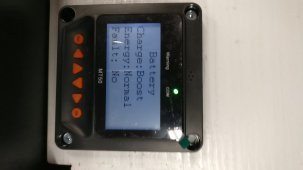
Maybe start with default settings - reset everything back to factory default on the charge controller. Disconnect panels, connect SCC to your batteries so it selects 24V nominal, reset defaults, then set to lifepo default. See what you get with them. You should not have to fuss with it much for basic lifepo charging.

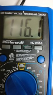
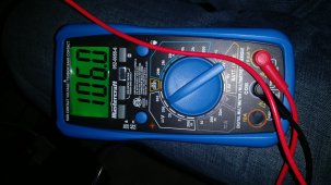
And yes, you will/should get full volts reading from the panels on your charge controller even if there isn't enough solar gain to put thru much current. I have the same Tracer controller with 2 panels in series, 12v, they are about 43 volts together. Early in the day I might see full voltage but only a half an amp or so coming in, but maybe 2 amps charging when it converts the power to 12v nominal. As soon as your panels can put thru some current your controller will optimize what it gets for charging. It took me a bit to understand what I was seeing on the charge controller.

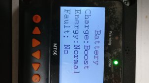
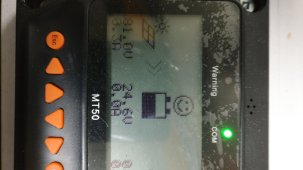
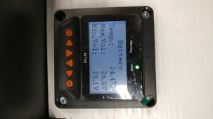
And it thinks the full charge voltage on the batteries means it's fully charged. So it will soon show 100%, but it's still charging. After sun down, when the pack settles to rest state, full charge is and should be 12.7 volts - FLA batteries - but the charge controller will now say it's at 58%!

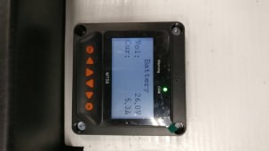
I'm going to install a full flow meter with shunt to better monitor amps in and out. That way, when you tell it how much you CAN have, and when amps out reaches empty, you get an accurate SOC percentage.

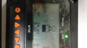
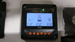
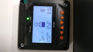
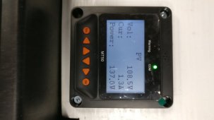
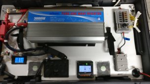
This one looks normal - it shows your panels coming in at 108V - 1.3A, and your charge going out at 26V - 5.4A. Looks perfect - exactly what mppt is supposed to do. You're just not getting a lot of solar gain/energy. It's mid-winter!!
5.4 out from 1.3 in is pretty darn good.

img_20211219_114751-jpg.76777
 
Last edited:
Batt. Type: User
Batt. AH: 206 AH
Temp. Comp Coef: 0
Rated Voltage: 24V
Over Volt Disc.:29V
Over V Disc: 29V
charge Limit: 28.9V
over V Rec: 28V
Equal Chg: 27V. Equalization should be turned off because your batteries are LiFePo4.
Boost Chrg: 27V. Try setting it to 28V.
Float Chrg: 26.5V. Try 27.20V (13.60V per battery)

Boor Rec:26.4V
Low V Rect: 23.2V
Under V Rect: 24.1V
Under V Warn: 24V
low V disc:22.4V
discharge limit:22V
equalize time: 10min
boost time: 180min

As shown in your pictures:
PV input Voltage is 108.5V, Current being PULLED from panels is 1.3A = 141.05W of power input.
Battery Voltage is 26V and charging current is 5.0A = 140W of power.
That look normal.

Also try running heavy load to see if the charging current will go up.
 
even if the voltage from all my panels is around 114V...it doesn't directly mean you're getting top amps as advertised on the panel
Not too long after sunup on a clear morning my 3S2P panels will display 10 or 12V and no amps. A short while later 50-60V and maybe 0.5A.
Once the sun is well up it will be more like 3-4A at 55-60 volts and like 13.5V at 18-20A into the batteries. I’ve seen voltage as high as 66V. I’ve also seen ~32/33A charging.

The point is only in absolutely perfect conditions at maybe below freezing will your panels even come close to their own labeled output. You didn’t get ripped off, there’s a lot of things at play.
 
Back
Top