diy solar

diy solar

Help me decipher Victron's circuit protection guidance for their solar charge controllers

Dzl

Unofficial Forum Librarian & Perpetual Newbie
Staff member
Moderator
Joined
Dec 10, 2019
Messages
5,108
Location
West of the rockies
Can someone help me translate this into plain english? (this is the advice Victron gives Re: circuit protection for all of their MPPT controllers)
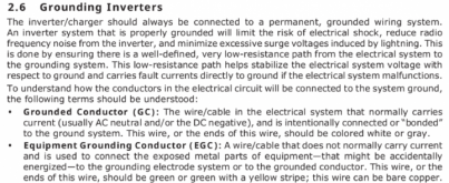
  • Provide a means to disconnect all current-carrying conductors of a photovoltaic power source from all other conductors in a building or other structure
  • A switch, circuit breaker, or other device, either ac or dc, shall not be installed in a grounded conductor if operation of that switch, circuit breaker, or other device leaves the grounded conductor in an ungrounded state while the system remains energized.

My best attempt at deciphering this is:
You should have a dual pole circuit breaker or switch to disconnect both the positive and negative wires between your PV array and your charge controller, unless your negative wiring is bonded to ground (as it normally is) in which case you should only have a breaker/switch on your positive wire.

I interpret:
  1. current-carrying conductors: to mean any wire that normally carries current (i.e. positive, and negative, but not ground)
  2. grounded conductor: 'current carrying conductor' bonded to system ground in a grounded system (in most cases the negative wire).

Link to manual (text in question is on page 6)
 
Last edited:
I do not believe you should be bonding negative to ground. It normally is only in an automobile, and that is a cost saving feature, not a safety feature. A number of reasons:
If you are using a SPD it needs to be grounded. The negative should not be attached to the same ground as the SPD.
In order for GFCI devices to work they rest of the circuit needs to be isolated from ground.
Certainly, in an A/C circuit, neutral needs to be separate from ground.
In my RV design, ground is ground, and it will be truly grounded into the earth by a rod whenever I set up camp. Negative is negative, positive is positive, hot is hot, and neutral is neutral.
That is the only way all the safety devices are going to work properly.
 
I do not believe you should be bonding negative to ground. It normally is only in an automobile, and that is a cost saving feature, not a safety feature.

I think you are confusing using the chassis as the negative return path (as automobiles do) with bonding negative to ground at a single point usually the negative battery terminal or negative busbar (which is what I'm talking about). Current would not normally flow through the chassis, it is roughly comparable to earth-ground in a residential system in this sense.

As I understand it both how your RV is designed (isolated or "floating") and what I'm talking about (non-isolated / chassis-grounded) are acceptable and there are pros/cons to either arrangement. I'm not 100% confident I'm using the correct terminology, but I am 100% sure what I am referencing is an acceptable (and common) configuration.

Here is an example of a grounded off-grid system with ground connection of the negative battery terminal (taken from the Victron e-book Wiring Unlimited):
Screenshot_2020-04-23 Wiring-Unlimited-EN pdf.png


1586378034347.png
1586381431910.png

-
-
 
No conflict. They should have said Earth Ground.
Grounded conductor is not normally a current carrying conductor for a building or structure. I.E. protective conduit, or 3rd wire: bare or green.
 
Grounded conductor is not normally a current carrying conductor for a building or structure. I.E. protective conduit, or 3rd wire: bare or green.
This conflicts with my understanding of the terms. And I'm reasonably sure of my basic understanding on this point.

Grounding conductor is the non-current carrying safety wire (green, green-yellow, or bare copper). Grounded conductor is a current carrying conductor (neutral or negative) that is connected to ground. In a grounded system, the grounded conductor is the side of the system that is referenced to ground.

See here, or see bullet points 1 and 2 in the attached screenshot.
 

Attachments

  • Screenshot_20201204_180258-1.png
    Screenshot_20201204_180258-1.png
    271.3 KB · Views: 3
Back
Top