diy solar

diy solar

Generator manual transfer switch and inverter with bonded neutral

48Rob

New Member
Joined
Nov 4, 2023
Messages
69
Location
61802
I have a “farm panel” electrical setup where main power from the utility feeds the meter and a main breaker set on a pole in the yard. The house and barn are fed separately from this main panel. The house and barn each have a sub panel, with a main breaker.

The ground and neutral are bonded in the main farm panel, and are not bonded in the house or barn sub panels. The only ground rod is below the main farm panel.

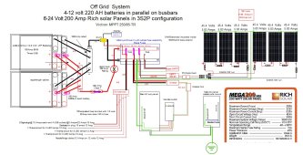
I am working on a non grid tie system for the barn. Solar panels, 880 Amp hours capacity of 12 volt batteries, and 2000 watt inverter.

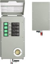
Beyond a few direct 12 volt accessory outlets, I want to feed a 4 circuit manual generator transfer switch from the inverter. Something similar to the switch shown, or a 30 Amp switch.

This would allow inverter feed, as well as generator feed (not at the same time).

The total load of the 4 circuits combined (all items on a circuit running at the same time) does not reach the 16.66 Amp maximum available power of the inverter. Max draw is in the 14 Amp range.

It is my wish to run general lighting circuits 24 hours a day using the solar/battery system (2 Circuits). This draw is around 6 Amps and is to be able to use/exercise the solar panels and system while keeping a hefty reserve. This would use roughly 85-90 Amp hours per 24 hour period.

The other 2 circuits would be available for running a fridge, furnace blower, etc. in a power outage.

I have on hand a Rich solar 2000 Watt pure sine wave inverter, with two outlets. The thought was to run a 10/2 cable from the inverter into a breaker box with 20 Amp breaker, then to the transfer switch (about 30’ away) in conduit where exposed, and install a plug and socket on the ends.

I have a #8 ground cable running from the #6 on the solar array, connected to the negative bus bar, inverter chassis ground, all other equipment grounds, and then to the ground bar in the barn’s AC panel.

The inverter does not have a wire connected to the ground terminal on the sockets. By grounding the inverter chassis to the main AC ground bar, am I safe with this system? There is no info in the owner’s manual, and Rich solar must be swamped as they haven’t responded.

The AC circuits I am connecting to in the AC panel have a typical ground, neutral, hot setup. When I transfer from AC to inverter, that neutral and ground, which is not connected in that sub panel, but in the farm panel, would then be “bonded”, because of the tie in with the inverters grounded chassis, right?
 

Attachments

  • 61nZEO9-yyL._AC_SL1500_.jpg
    61nZEO9-yyL._AC_SL1500_.jpg
    65.3 KB · Views: 0
The ground and neutral are bonded in the main farm panel, and are not bonded in the house or barn sub panels. The only ground rod is below the main farm panel.
As it should be
The total load of the 4 circuits combined (all items on a circuit running at the same time) does not reach the 16.66 Amp maximum available power of the inverter. Max draw is in the 14 Amp range
so running so close to inverter output my suggestion would be to use a Victron SCC or better quality inverter. If you are not going to do the higher end equipment but still run so close to 100% I’d go at least 2500W for the inverter.
thought was to run a 10/2 cable from the inverter into a breaker box with 20 Amp breaker
So the wire is adequate but the 20A circuit breaker will never blow in the event of a short or other fault. I would use a 15A breaker myself but, no, actually not I would use a 3000W or 2500W and fuse/breaker accordingly.
have a #8 ground cable running from the #6 on the solar array, connected to the negative bus bar,
Ground as in a third wire?
Otherwise that should not go to the busbar
The AC circuits I am connecting to in the AC panel have a typical ground, neutral, hot setup. When I transfer from AC to inverter, that neutral and ground, which is not connected in that sub panel, but in the farm panel, would then be “bonded”, because of the tie in with the inverters grounded chassis, right?
im either misunderstanding you or more information is needed.
All good AIO’s bond neutral for inverter use, but open that connection when in grid/pass
 
I've been considering a 3000 watt inverter, not because I need that capacity, but to stay more in the middle of the range so as not to overtax the inverter. Is that a wise strategy?

There is no "third" ground wire. I will have a #6 bare ground connected to all solar panel frames, and connect it to an insulated #6 ground wire that runs through conduit to the rest of the system and terminates at the barn's AC panel in the ground lug.

I am new to all this and am unsure of the terminology "AIO".
Is this something a larger, higher quality inverter would have that would correct the potential issue that I believe I have with the way the current inverter bonds neutral and ground inside the inverter?
 
The ground and neutral are bonded in the main farm panel, and are not bonded in the house or barn sub panels. The only ground rod is below the main farm panel.
You might want to draw this and your bonding plan for us to comment.

It's arduous to read bonding plans in words but from this paragraph I'd probably be planning an unbonded inverter and having everything always use the main panel bond.
 
that a wise strategy
Yes
will have a #6 bare ground connected to all solar panel frames, and connect it to an insulated #6 ground wire that runs through conduit to the rest of the system and terminates at the barn's AC panel in the ground lug
’codes’ may require that. I’d consider that myself. I’d more likely ground the panel frames at the panels.
However I personally would not run the panel frame ground to the charging system / battery bank busbar. Ever.
new to all this and am unsure of the terminology "AIO".
All In One - AIO
This is a multifunction unit that contains a charge controller, a ‘utility’ battery charger (convenient for generator charging), solar charge controller, and an inverter.
Is this something a larger, higher quality inverter would have that would correct the potential issue that I believe I have with the way the current inverter bonds neutral and ground inside the inverter?
AIO’s are available at all levels of quality. Most of these do the Nuetral-Ground bond internally while in offgrid battery/inverter mode, but open the N-G bond when external 120/240V is present (feeding the unit). Some need to have a screw removed to disable the internal bond. Some (few) are not bonded at all in any mode.

Standalone inverters or inverter-chargers can be unbonded. Some cannot be bonded without damage.

Read the manual or contact a manufacturer to determine how to handle these configurations.
 
Thank you all.

After further reading and watching videos, I have a better understanding of the advice you have offered, and of the constraints of my system-as planned.
In short, my cheap internally bonded inverter is not suitable for use with a transfer switch because there cannot be more than one neutral/ground bond in a system.

Many of the higher quality All in one units automatically switch the neutral/ground connection from the AC panel, to the inverter, this allows "two" neutral/ground connection points, but one one is connected at a time.

It appears that the AIO units offer automatic switching from grid-to inverter, battery charging, and other functions. This is all far more than I need, or can afford at this point. I am after manual switching without extra bells and whistles.

I can afford to purchase a better quality inverter.
My research shows that in order to be able to connect my battery/inverter system to a transfer switch in order to use a few existing circuits in my main AC-grid panel, I need to purchase an "un-bonded" inverter.

Are any of you aware of, or using a 3000 watt pure sine wave inverter that offers this option, in an affordable price range? Affordable to me is around $800-$1000

To recap, my stand alone system is intended to power a few 12 volt accessory outlets, and run a few light on a regular basis, and be able to run a couple critical loads in an grid down power outage.
My original plan was to use the cheap inverter to power a few stand alone outlets, which the critical loads could be connected to in an outage.
Further research showed that connecting an inverter to a transfer switch would accomplish the same result, with far less wiring/effort.

Am I correct thus far in my basic understanding?
 

Attachments

  • capture7.jpg
    capture7.jpg
    261 KB · Views: 17
Last edited:
my cheap internally bonded inverter is not suitable for use with a transfer switch because there cannot be more than one neutral/ground bond in a system.
Just use a transfer switch that switches bare/Green/ground?
 
This is all far more than I need, or can afford at this point. I am after manual switching without extra bells and whistles.

I can afford to purchase a better quality inverter.
So if you purchase a ‘quality inverter’ and a transfer switch you’re probably going to be only a few pizza$ away from an MPPSolar AIO …
Am I correct thus far in my basic understanding
My opinion is that- my opinion.
But I try not to make my choices based on dollar$ but rather I put effort to make my choices based on expense versus benefits.

Less dollars spent is often way more costly than solving for goal. And cost = expense. Mere Dollar$ don’t factor for what you lose overall or further down the road.
 
Last edited:
I agree that not worrying about cost is sometimes the wiser choice. For now, for me, cost is weighing heavily on my decisions. I'm new to solar, am trying to get my feet wet and learn.

An AIO would be advantageous for some, and maybe even me, but I already have a charger for my camping trailer system. I don't want to have the grid automatically provide backup power to my system, or charge my batteries.

In researching inverters yesterday, I find I was in error in my belief that a quality inverter could be had for a grand or less. $4K+ seems the going rate for an AIO that would run a small system.
I do appreciate your suggestions, and the time and effort you've put into helping me, as well as your opinion.

Everything is easy, once you know how...
I just want my inverter to power a few circuits in the barn's AC panel, with the ability to easily transfer from one to the other, manually.

Just use a transfer switch that switches bare/Green/ground?

Your words in the quote give me hope that I can indeed accomplish my goal :) I just haven't found the detailed instruction that explains what type of transfer switch to use, and more importantly, to completely understand how it all works so I can safely install it.
 
I find I was in error in my belief that a quality inverter could be had for a grand or less. $4K+ seems the going rate for an AIO that would run a small system.
Maybe I need to read back for capacity requirements but there are inverters far less than $4k- there’s even dependable AIO’s under $1000

FWIW:
Most AIO’s do not require a grid connection, either. I use a 1012LV-MK ($632) offgrid and the ‘grid charger’ takes my generator input. There’s 2.7kWh to 5kWh AIO’s available under $1000 that aren’t junk, too.

Top-tier is $4k and more for just an inverter. Victron’s not terribly priced either and they are upper shelf products
 
Last edited:
Back
Top