diy solar

diy solar

Help me with my solar settings please for lithium cells

mystic pizza

New Member
Joined
Jun 20, 2021
Messages
134
I have lifep04 cells connected as a 12V bank separated by a switch connected to a 12 V lead acid battery bank.

The system is currently set to only charge from solar cells (4 x 250W) in a 2x2 array fed into 2 separate 30A mppt charge controllers.

I have set each controller to have a boost voltage of 13.8V, duration 30 minutes, a float voltage of 13.4 V and a boost reconnect of 13.3V.

As I understand it, that should mean the banks should charge until a voltage of 13.8 V is reached and held for 30 minutes before dropping to a float voltage of 13.4V. When the voltage then falls to, or perhaps below 13.3V the system charges again until the boost voltage of 13.8V is reached,which as I understand it, should mean the lifep04 bank is at 99%capacity.

What appears to happen though is the controllers go into float before the batteries reach 13.8V,and the MT50 meter connected to the controller shows 0.2V higher than the battery voltage.


Why is it going to float too early?


Do my settings sound reasonable?

What can I do to stop one mppt controller floating too soon? As far as I know they cannot be connected to 'talk' to each other.

Thanks
 
I have lifep04 cells connected as a 12V bank separated by a switch connected to a 12 V lead acid battery bank.

The system is currently set to only charge from solar cells (4 x 250W) in a 2x2 array fed into 2 separate 30A mppt charge controllers.

1000W on a 30A controller charging a 12V system will never produce more than 30A * 13.8V = 414W

If you have a SINGLE 1000W 2S2P array connected to BOTH controllers, that's wrong. You need to have two completely separate arrays for each controller.

I have set each controller to have a boost voltage of 13.8V, duration 30 minutes, a float voltage of 13.4 V and a boost reconnect of 13.3V.

13.8V can be okay. For LFP, depending on the charge rate, a very long absorption period is required to achieve near 100% SoC. For lead acid, 13.8V must be maintained for a VERY long time to achieve full charge. 13.8V is more typical for a standby application, e.g., a UPS that is only occasionally cycled.

13.4V is possibly low for a float charge. Check your battery specs.

As I understand it, that should mean the banks should charge until a voltage of 13.8 V is reached and held for 30 minutes before dropping to a float voltage of 13.4V. When the voltage then falls to, or perhaps below 13.3V the system charges again until the boost voltage of 13.8V is reached,which as I understand it, should mean the lifep04 bank is at 99%capacity.

You have the concept correct, but the bold part depends on the charge termination current/absorption period. Based on your system, I really doubt it.

What appears to happen though is the controllers go into float before the batteries reach 13.8V,and the MT50 meter connected to the controller shows 0.2V higher than the battery voltage.

The MPPT is measuring battery voltage in response to any charge current present, so it's usually a little higher than an open circuit voltage measurement with a voltmeter.

Why is it going to float too early?

Does your MPPT also have a tail current?

Do my settings sound reasonable?

No.

What can I do to stop one mppt controller floating too soon? As far as I know they cannot be connected to 'talk' to each other.

Nothing. Multiple chargers are typically only beneficial in boost/bulk. Once it's in absorption, the battery can only accept what current it needs to maintain the voltage. Very common for all but one charger to drop to float during absorption.
 
If you have a SINGLE 1000W 2S2P array connected to BOTH controllers, that's wrong. You need to have two completely separate arrays for each controller.
2 panels into one 30A mppt controller, two into the other. I know ideally they need to be bigger controllers, but funds dictated smaller ones at the time and living in the UK, they will never reach their max output anyway.

Does your MPPT also have a tail current?
I don't think so. They are Tracer 2215 BN (well, actually they are badged as outback)


Given the information, can you suggest better setting please. The cells are Winston thundersky 40 Ahr cells (TS-LFP40AHA). Thank you.
 
I should add that the batteries generally have a load on them which I guess pulls the voltage down a bit. The balance start voltage for the lithium seems to be set at 3.2,which may be a bit low. Perhaps I bed to increase my boost voltage a bit to compensate for the load?
 
2 panels into one 30A mppt controller, two into the other. I know ideally they need to be bigger controllers, but funds dictated smaller ones at the time and living in the UK, they will never reach their max output anyway.

that's fine. Arrays don't often perform at max, so you're not losing much.

I don't think so. They are Tracer 2215 BN (well, actually they are badged as outback)

HUH?

Given the information, can you suggest better setting please. The cells are Winston thundersky 40 Ahr cells (TS-LFP40AHA). Thank you.

So you have a 7P4S battery bank?

I should add that the batteries generally have a load on them which I guess pulls the voltage down a bit. The balance start voltage for the lithium seems to be set at 3.2,which may be a bit low. Perhaps I bed to increase my boost voltage a bit to compensate for the load?

Yes, that is very low. Balancing should generally not start much below 3.40V.

Please help us understand how you use the two banks and if you use them connected together.
 
They are Outback flexmax 30's, which I believe are the same as Tracer 2215BN.


So you have a 7P4S battery bank?
Yes


Yes, that is very low. Balancing should generally not start much below 3.40V.

Please help us understand how you use the two banks and if you use them connected together.
Yes, seems a bit low to me.

Ok. The two banks are separated by a BEP motorised switch. The switch is controlled by a Xantrex link pro battery monitor to disconnect the lithiums from the LA at a certain voltage. The charge sources and loads are connected to the LA bank. The idea being a first level of protection for the lithiums before the BMS cuts in.

The LA should remain fully charged (12.8V), and can be charged by an engine driven alternator, or a mains battery charger.

The lithiums are only charged by solar.

The main load on the Lithiums is through a Xantex inverter running a freezer, but other smaller 240V loads, and DC loads are also connected.

I suspect that all sounds a bit odd, but there it is.

ETA, in normal use, the banks are connected together.
 
They are Outback flexmax 30's, which I believe are the same as Tracer 2215BN.

Wow. Find no reference to them on Outback's website.

Yes, seems a bit low to me.

Typical settings for maintaining balance on healthy battery is: 3.40V, 20mV difference, only during charge.

Ok. The two banks are separated by a BEP motorised switch. The switch is controlled by a Xantrex link pro battery monitor to disconnect the lithiums from the LA at a certain voltage. The charge sources and loads are connected to the LA bank. The idea being a first level of protection for the lithiums before the BMS cuts in.

So, like this?

charged in parallel until 13.8V
disconnected @ 13.8V
280Ah LFP charged at 13.8V for 30 min @ 30A max on its own MPPT.
440Ah Lead-acid charged to 13.8V for 30 min @ 30A max on its own MPPT.

The LA should remain fully charged (12.8V), and can be charged by an engine driven alternator, or a mains battery charger.

12.8V is a resting unloaded/uncharged voltage?

The lithiums are only charged by solar.

The main load on the Lithiums is through a Xantex inverter running a freezer, but other smaller 240V loads, and DC loads are also connected.

I suspect that all sounds a bit odd, but there it is.

A bit.

ETA, in normal use, the banks are connected together.

ETA?
 
Wow. Find no reference to them on Outback's website.
Not sure what to say, except i think they are made by Tracer and then branded by Outback. If you google for them, you will find they look identical to the tracer offerings. The reason I called them Tracers is that more people are likely to be familiar with the Tracers, and hencer their settings.
Typical settings for maintaining balance on healthy battery is: 3.40V, 20mV difference, only during charge.


Ok, will up the value a bit. Its a Overkill type BMS, so is quite configurable.
So, like this?

charged in parallel until 13.8V
disconnected @ 13.8V
280Ah LFP charged at 13.8V for 30 min @ 30A max on its own MPPT.
440Ah Lead-acid charged to 13.8V for 30 min @ 30A max on its own MPPT.


No, they are not disconnected unless the low voltage disconnect or high voltage disconnect is reached as per the settings in the battery monitor. Both controllers are connected directly to the LA batteries.
12.8V is a resting unloaded/uncharged voltage?

Yes, it is, and if the lithiums are at the lower end of their capacity then I guess some load on the system may eat into the capacity of the LA's.


I added the ETA in case it wasn't obvious that the banks are connected together in normal use.

Thanks for your help
 
What are the high/low disconnects for splitting the banks?

So, 60A max is charging 280Ah LFP + 440Ah of LA.

IMHO, you're almost certainly damaging your LA battery bank with this charging scheme. Regular cycling requires charging to the absorption voltage typically with a 4+ hour absorption. 13.8V is only acceptable for standby operations as it takes days to get them fully charged. 100% charge of LA is mandatory to ensure proper cycle life.

Given my understanding of your system, I would proceed as follows:

Charge to LA specified absorption voltage 2+ hour absorption (however long it takes for tail current to drop to 9A).
Disconnect banks at the lower of 14.4V or 0.2V BELOW absorption voltage to prevent holding the LFP at peak charge unnecessarily.
Float at the lower of 13.6V or LA float charge spec.

This should improve the health of the LA with no impact on LFP life.
Many thanks for taking the time. I shall have to give it a bit more thought, but your suggestion sounds like an option.

The LA aren't as badly treated as they might be, as I tend to charge them once a week using the mains battery charger.
 
Many thanks for taking the time. I shall have to give it a bit more thought, but your suggestion sounds like an option.

The LA aren't as badly treated as they might be, as I tend to charge them once a week using the mains battery charger.

Every second LA batteries are not at 100% SoC, they are deteriorating. Failing to charge them to true 100% permits sulfation to occur. This reduces capacity. Light sulfation on flooded batteries can be corrected by equalization charges, which are typically done at 15.6-16.2V. AGM and GEL sulfate more slowly, but it's permanent.

If your depth of discharge is very shallow, deterioration will be diminished.
Understood. Many thanks. To be honest the LA's are on their last legs anyway.
 
Once you have the LA out of the picture:

bulk/boost/absorption: 13.8V
absorption time: 4-6 hours (find where your charge current current drops to 5A)
float: 13.6V
That is the ultimate goal. I have the problem of the alternator charging and suitable battery charger to tackle first.

I suppose i could connect the solar and loads directly to the lithium cells, but would then be reliant on the BMS solely to protect the lithium cells and lose the benefit of the BEP switch.

Anyway, you have given me a few things ti thinks about, so thanks for that.
 
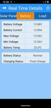
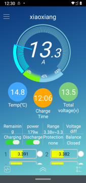
So, today's reading make little sense to me. Attached two screen shots. One from the wifi device connected to one of the mppt controllers, and one from the BMS software. Both taken at the same time. Solar is charging, and the system has some small loads on.

I was expecting the current to fall to zero in float mode, but it appears not to have. ANy ideas pls?

Screenshot_20220325-122608.pngScreenshot_20220325-123053.png
 
Back
Top