diy solar

diy solar

HELP on wire sizes

aluchipawa

New Member
Joined
Oct 5, 2021
Messages
35
Hi new friends.
I am getting together a solar system that I will be integrating into my RV's existing electrical system. I am putting the battery, inverter, and charge controller about 12-15 feet from the DC and AC Fuse boxes from the old system. The system consists of
206Ah Sok LiFePO battery
Giandel 2200W Inverter
2 Rich Solar 200W panels
Rich Solar 40A charge controller.

On the existing AC Panel there is an ATS between shore power and the generator. I am planning on disconnecting the generator from the original ATS and then adding an ATS Which will choose between the inverter and the gen and then connect that where the generator was connected in the original ATS (Hope that makes sense). So the inverter will need to connect to the new 30Amp ATS which is about 15 ft away. Would 8AWG wire be sufficient to connect the inverter to the new ATS?

Secondly, the existing DC fusebox has a 30A main fuse in the box itself. Being that this is also 15ft away would 8AWG wire be fine? I will have a 200A Fuse on the +lead from the battery where I will be connecting the inverter and the + that will go to the DC Fusebox.

For the main components I will be using 4AWG to connect the battery to inverter (Through the 200A Fuse), battery to a negative busbar, busbar to inverter and then will be using 6AWG wire from the Charge Controller to the battery. Is right with the components I have?

I know its a lot of questions but I really appreciate any help I can get since this will be my first solar setup. THANKS Y'ALL
 
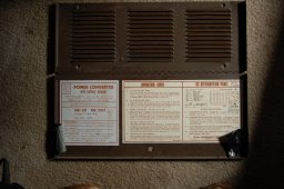
Is there a converter in the ac/dc distribution panel?
If yes please post a picture of the converter so that we can see the make model and amp rating.
As for putting the main system 15 feet from the converter... voltage drop is going to be an issue.
Please also provide pictures of the ac/dc distribution panel showing the ac breakers and their map and do the same for the dc side.
 
As for the inverter.
2200 ac watts / .85 conversion factor / 10 volts low cutoff = 215.68627451 service amps
215.68627451 service amps / .8 fuse headroom = 269.607843137 fault amps.

You will need 2/0 awg minimum between the inverter and the battery.
Also that battery will be pushed very hard to supply ~215 amps.
Better check the c rating on the battery.

Regarding the ats, you mention a generator and an inverter, will you require the option to connect to shore power?

Also is this a trailer or a coach?
 
Last edited:
Is there a converter in the ac/dc distribution panel?
If yes please post a picture of the converter so that we can see the make model and amp rating.
As for putting the main system 15 feet from the converter... voltage drop is going to be an issue.
Please also provide pictures of the ac/dc distribution panel showing the ac breakers and their map and do the same for the dc side.
There is a converter in the distribution panel but I want to disconnect it so that When I am using the inverter, it isn't just recycling that power back to 12v and back to the battery. I plan on just charging the battery through the solar panels &charge controller for now. Our first trip will be Arizona so I think we should have plenty of sun to charge batteries
 
There is a converter in the distribution panel but I want to disconnect it so that When I am using the inverter, it isn't just recycling that power back to 12v and back to the battery.
I ask about the converter so we can properly size the dc feeder wires to the dc distribution panel.

I plan on just charging the battery through the solar panels &charge controller for now. Our first trip will be Arizona so I think we should have plenty of sun to charge batteries
You didn't answer my question about shore power and have not supplied and pictures.
Understood.
 
As for the inverter.
2200 ac watts / .85 conversion factor / 10 volts low cutoff = 215.68627451 service amps
215.68627451 service amps / .8 fuse headroom = 269.607843137 fault amps.

You will need 2/0 awg minimum between the inverter and the battery.
Also that battery will be pushed very hard to supply ~215 amps.
Better check the c rating on the battery.

Regarding the ats, you mention a generator and an inverter, will you require the option to connect to shore power?

Also is this a trailer or a coach?
Sounds good I will get the 2/0AWG. This is a coach. So my plan with the ATS is to have one ATS that chooses between gen and inverter. That ATS will then feed into another ATS that chooses between the first ATS (inv/gen) and shore power.
 
I ask about the converter so we can properly size the dc feeder wires to the dc distribution panel.


You didn't answer my question about shore power and have not supplied and pictures.
Understood.

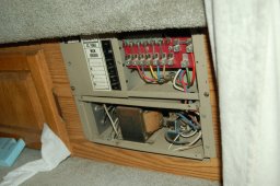
In the post above I explained about shore power and here is the DC Distribution power and converter. I appreciate your help!


DSC_0014.JPGDSC_0015.JPG
 
By the look of that lug I doubt 1 awg will fit.
There are options though.
 
Ok so a 45 amp converter.

45 amps, 60 foot round trip@12 volts = 1 awg wire to get < 3% voltage drop.

This tool will allow you to experiment https://baymarinesupply.com/bosns_corner_wire_sizes
Gotcha. If I plan on disconnecting the converter and just using the DC Distribution panel which has a main 30 amp fuse would I be able to use higher gage wire? I don't want to use the converter because its old and I am going to be using a LiFePO battery and I am thinking it would not charge it properly.
 
Gotcha. If I plan on disconnecting the converter and just using the DC Distribution panel which has a main 30 amp fuse would I be able to use higher gage wire? I don't want to use the converter because its old and I am going to be using a LiFePO battery and I am thinking it would not charge it properly.
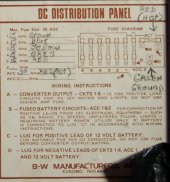
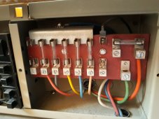
The lug on the dc distribution panel looks like it will accept 6 or 4 awg max.
You could do a 24 volt system and put a buck converter close to the distribution panel.
 
I did the math and at 24 volts the voltage drop is <3% using 6 awg wire.
 
That wiring looks very old, might be chassis return.
Suggest you verify that by going to an accessible load and seeing if there is a return wire or if it just goes to the chassis.
 
Here is a more detailed look at the DC Panel. I'm not sure if the loads return or not. I can see that the water pump and the water heater both have lead wires and a return wire, but the wires disapear under the bathroom and it is hard to determine where the return ends up. Sorry I am very new at this I hope I am making sense.

DC.jpg20211008_131437.jpg
 
To check for chassis return...
1. make sure there is no power to the dc distribution panel.
2. unscrew the 2 fasteners that anchor the fuse block.
3. inspect the area behind the area behind the fuse block.

If you find a negative busbar with wires corresponding to the fused wires then its not chassis return.
If you don't find the negative busbar then I'm sastisfied that its a chassis return setup.
 
I'm pretty sure this is chassis return as there is only one wire going to lug "D" and it is green.
 
You are correct sir! I looked behind and there is no busbar. Also when I looked under the hood, the negative on the house battery is connected to the frame. I'm curious how they managed to use such a small wire to connect the battery to the DC panel since the battery is more than 20 ft away from the DC panel
 
You are correct sir! I looked behind and there is no busbar. Also when I looked under the hood, the negative on the house battery is connected to the frame. I'm curious how they managed to use such a small wire to connect the battery to the DC panel since the battery is more than 20 ft away from the DC panel
I guess they figure the frame is a good conductor.
From the picture that green wire is probably 10awg, which is probably ok.

You might try using the frame as the return path from your new system.
Probably should upgrade that ground wire.
Also from the manual there is a relay that switches between converter and battery power.
Might be a good idea to bypass that for lower resistance, but all the optimizations can be done after the juice is flowing, if necessary.
How big of a wire will that ground lug on the dc distribution panel take?
 
The ground lug and positive lead lug are both 5/16" in diameter. On a related note, since I want to disconnect the converter, is there anything I need to do beyond disconnecting all the wires from converter to the AC panel and the DC panel?
 
Back
Top