diy solar

diy solar

Help please - Can’t get Solar Assistant to give details on EG4 LL v2 batteries

And for some other possibilities, I am making the assumption that you have SA connected directly to the batteries, right? and not just to the inverter? If connected only to the inverter, you have to use the EG4 protocol, and ID the batteries starting with ID 1, then go up from there.

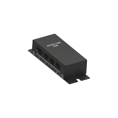
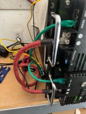
If you have SA connected to the batteries themselves, then the batteries need to be interconnected with standard network cables, and then SA connected somewhere in that string. SA can be at either end of the battery string.

It should be noted that if SA has visibility to the batteries, then you lose the EG4 inverter managing the batteries. not that it's a problem, just note that you need to configure all of your battery settings like charge rate, float voltage, etc. in the inverter manually after you set the battery type to user.
 
Thanhrodke: thank you for your detailed and helpful replies. I have been sidelined for a while now with heart issues secondary to covid. I am hoping to re-focus on this SA/LL V2 issue in the next couple of weeks. My batteries are V2, with the new style screen and breaker, but only 4 DIP switches, which is what the version of the manual which came with my V2's does describe. I did have my inverter set to "user", and did have one of the yellow cables connected directly from "B2" to the RP running SA. The com5 and com 7 ports seemed to me to be an arbitrary deal with the laptop I was using, because as I recall (from weeks ago now), when both batteries did show up on the BMS software, even on com5 and 7, they showed up as B2 and B3, which was correct at that time. I need to go back and verify this. The fundamental conflict between SA and EG4 software as regard B1 or B2 being required for the host is very frustrating. At least for now I can see one battery, but I do still want to get this to work properly. Hopefully soon I will be able to essentially start over with my troubleshooting. Thanks again.
 
I hope you are back to full strength real soon!

so let's target the basics with a checklist; note that I don't have your same setup, I am gathering some of the details below from the manual, and just offering another set of eyes.
  1. Batteries configured with ID 2 and ID 3 (however you think the DIP switches should be set to get there) and each battery rebooted after the configuration
  2. SA up and running and the web page accessible on the network (the Pi may not post/boot if it loses power while the battery connection is alive; it's a bug and depends upon the model of Pi that you have)
  3. The inverter should be set to battery type User
  4. One USB cable from the SA Pi to the inverter
  5. One USB to RJ-45 cable to the ID 2 battery in the RS-485 port; this should have come with the batteries
  6. RJ-45 to RJ-45 (standard network cable, not a crossover) to connect the Battery-Comm interface of the battery to each other
  7. In SA, go to the configuration tab, in the Inverter section, select the inverter USB port, which should be something like "DIRECT-USB# Voltronic"
  8. In the Battery selection, select the USB Modbus RS232/485 in the dropdown, then the USB port, which should be something like "USB#-USB Serial"
  9. The Inverter section should say "Connected" pretty quick in the status section
  10. The battery section may take a couple seconds for it's status to change to Connected, as SA connects to batteries sequentially (across my 12 batteries, I just timed it as about 40 seconds, so a little over three seconds per battery).
Good luck!
 
Thanhrodke. Again, much appreciated. I just went through your checklist, line by line. All the settings and all the cables were correct. I get “connected” for both the inverter, and battery, but I can still only see ONE battery. See attached screen shot of battery detail page from SA dashboard. Soooooo frustrating. This should not be this difficult. I will try again next weekend. Thank you for your help. Tom
 

Attachments

  • F3C379A6-E944-4726-B247-6092AE89E8D7.png
    F3C379A6-E944-4726-B247-6092AE89E8D7.png
    1.1 MB · Views: 40
I fought this same scenario with my Growatt and EG4LL, only until I installed a multi-port ethernet splitter and run separate RJ45 cables to each RS485 port of the batteries starting with ID#2 onward did all my packs appear. All daisy chain cables were removed and the BMS cable from the Growatt disconnected as well.

Similar to these instructions:


In my case I chose USB modbus/rs485 protocol in SA battery config.

Splitter used:
 
well that would be terrible if their own daisy chaining does not work. I would definitely give it a go for all four combinations of cabling between the two batteries. be sure to disconnect and reconnect SA after each recabling.
  • bottom port on battery 1 to bottom port on battery 2
  • top port on battery 1 to bottom port on battery 2
  • bottom port on battery 2 to top port on battery 1
  • top port on battery 1 to top port on battery 2
here's a larger RS485 hub from signature solar if you see a future with more than two batteries:
Oh I am not saying it does not work, just not for me with direct cabling from a splitter in Solar Assistant if one wants information from each "pack". I had a third EG4LL V1 delivered yesterday but have not unpacked and installed that one yet. Also have on hand a second 4-port splitter but with the size of my system will probably just be running three batteries. Waiting for this snow to subside over 5" thus far.
 
Update: First of all - thank you to all those who posted in this thread trying to help me. Last week I bought the “splitter” referred to above. Today I finally had time to work with my system. With my EG4 LL V2 batteries set as position 2 and position 3, and my 6000EX inverter set to “User”, I plugged one of my EG4 supplied “green“ cables directly into the RS485 port of EACH battery, and then I plugged both other ends into the Splitter. I then plugged the EG4 supplied “yellow” cable into my RP running SA, and the other end into the 3rd port on the splitter. I had to disconnect and reconnect the batteries in SA and also had to try a couple of different ports on the RP. But, finally success!!!! For the first time ever I was actually able to see BOTH battery packs, with full details on each. Thank y’all so much for the help and suggestions. Hopefully this thread will help anyone else having this problem. It CAN be done. Tom
 

Attachments

  • CB82BBB6-048A-4C73-B4A4-1BAF6155CF67.jpeg
    CB82BBB6-048A-4C73-B4A4-1BAF6155CF67.jpeg
    229.3 KB · Views: 56
woot woot! glad you got it going and props to @OilCan for the splitter recommendation.

pretty irritating that the EG4 LL battery daisy chain doesn't actually work, or the documentation is so poor that none of us can figure out how to cable them properly.
 
So I'm following this thread.
I have EG-4LL V2, which have 6-position DIP switches.
The manual indicates that B1 should have ID1, but when I do that, BMS tools is a total mess when communicating with B1:
1676840792404.png
After reading, I set B1 to DIP position #2 and the rest of the batteries follow sequentially. I get sane text on BMS tools, but only one battery at a time.

Question:
What is the RIGHT way to daisy chain the com ports on the batteries? Or is this non-functional for batteries of these types if we're having to move to a splitter? I've watched various videos and I've seen it done a number of ways. The way I have it setup now:

B1 Battery to B2 Comm, B2 Battery to B3 Com, B3 Battery to B4 Com, etc... But (as others have found) I cannot see more than one battery at a time in BMS.


I have not connected these batteries (I have 6 of them) to an EG-4 inverter (6500EX-48). It sounds like I need a splitter, connect to each RS485 port on every battery, set the inverter to "user" - can anyone confirm?

It's a little disappointing that this seems to be a bit trial and error with the EG-4LL V2.
 
So I'm following this thread.
I have EG-4LL V2, which have 6-position DIP switches.
The manual indicates that B1 should have ID1, but when I do that, BMS tools is a total mess when communicating with B1:
View attachment 135699
After reading, I set B1 to DIP position #2 and the rest of the batteries follow sequentially. I get sane text on BMS tools, but only one battery at a time.

Question:
What is the RIGHT way to daisy chain the com ports on the batteries? Or is this non-functional for batteries of these types if we're having to move to a splitter? I've watched various videos and I've seen it done a number of ways. The way I have it setup now:

B1 Battery to B2 Comm, B2 Battery to B3 Com, B3 Battery to B4 Com, etc... But (as others have found) I cannot see more than one battery at a time in BMS.


I have not connected these batteries (I have 6 of them) to an EG-4 inverter (6500EX-48). It sounds like I need a splitter, connect to each RS485 port on every battery, set the inverter to "user" - can anyone confirm?

It's a little disappointing that this seems to be a bit trial and error with the EG-4LL V2.
Welcome aboard.
Interesting that they have gone to 6 DIP switches on the LL V2’s. My two batteries have only 4 DIP switches.
The only way that I could see more than 1 battery in the BMS SW was to have them separately cabled into separate USB ports using the SS “yellow” cables.
I never had any success with any combination of “comm” settings on the LL V2 batteries. Daisy chaining with the short green cables was futile.
I was never able to see both of my 2 batteries until I did the splitter the cables from the RS485 port instead of the Comm port.
Bear in mind that settings for EG Inverters and the BMS SW are totally different than what is required to communicate with Solar Assistant.
Good luck.
Tom
Tom,
Thanks. I have 6 batteries so cabling them into different USB ports is a bit of overkill. I can plug into them one at a time. I think it's ridiculous that this is not vetted in the instructions and that those instructions set the primary to an ID of "1" which is unusable with BMS.

In terms of inverter communcation - what's the next step here? Can I assume these will communicate with the inverter (an EG-4) in series or do they need to be paralleled out so the inverter can see all of them. Getting these charged from the inverters is where I'm going next.
 
I gave up on inverter communication. I went with Solar Assistant, and set my EG4 6000 to "user". With the splitter, I am now seeing both batteries in Solar Assistant. I wish I had 6 batteries. Jealous.
 
I gave up on inverter communication. I went with Solar Assistant, and set my EG4 6000 to "user". With the splitter, I am now seeing both batteries in Solar Assistant. I wish I had 6 batteries. Jealous.
Can you give me a little more details (I'm a noob on the power storage side). I thought the inverters HAD to communicate with the batteries in able to engage charge functions, etc?

I've asked Signature Solar for some tech support, but based on what I've been reading here their tech support isn't always responsive, I'll let you know if I get a response.
 
Since I never was able to get my Eg4 6000 in "EG4" mode to let me see all of my batteries, I was never sure what communication was actually occurring with my batteries, so I switched to "user" mode, and rely upon SA to get me details. The Inverter and BMS still "communicate", but apparently on a more limited basis. The Inverter does still control or at least participate in charging the batteries according to the bulk, float and low cutoff settings you manually enter as part of setting up "user" mode. I get all of the details about my batteries from Solar Assistant. This thread is about using solar assistant, and having it see all batteries.
 
Since I never was able to get my Eg4 6000 in "EG4" mode to let me see all of my batteries, I was never sure what communication was actually occurring with my batteries, so I switched to "user" mode, and rely upon SA to get me details. The Inverter and BMS still "communicate", but apparently on a more limited basis. The Inverter does still control or at least participate in charging the batteries according to the bulk, float and low cutoff settings you manually enter as part of setting up "user" mode. I get all of the details about my batteries from Solar Assistant. This thread is about using solar assistant, and having it see all batteries.
Got it, Pi with Solar Assistant. Thanks for confirming that "user" will get the batteries functional with the EG-4 and I appreciate the post here.
 
I ran into similar problems with the dip switch settings. One the one I was using, it has 4 dip switches on the side(maybe Version 1). It appears that not only is the dip switches upside down, but also "on" and "off" are backwards. I spent about an hour messing with it before I figured it out. For ID#1, had to set switch 4 to the "off" position, and the rest to "on".
 
Back
Top