diy solar

diy solar

Help?we’re lost!

Jamasarah

New Member
Joined
Apr 24, 2021
Messages
99
Location
Oregon
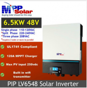
We purchased a MPP 6500W 48V all in one solar unit, 16, 250 Santan used panels, & 4 12v deep cycle marine batteries, & got them equally charged.
We Arranged 8 panels in series (or should they be in parallel? ) hooked everything up with the help of the manual & Will’s Tutorials.
BUT..... we thought ( manual being in Greek and all ) we had panel power and ran a few fans at night, and then in the morning, we got an error of 04, and a blinking red light?‍♀It is only getting power from the batteries & nothing from the panels?? So now the batteries are low & no power from the panels
HELP!!!!
 
What is the Voc of your panels and the max input voltage of your SCC?
The SCC may be shutting down (or burned out) from feeding too much voltage into it.
 
Not familiar with your gear, but this thread has the math worked out as an example, hope it helps!
 
Yes, SCC is the PV input of MPP.

8 in series would be around 300V.
After checking voltage specs as Sandals, suggested ...

another possibility is you have polarity backwards. Have a DMM? Check voltage and polarity at PV input of MPP. Be careful, lethal voltage and current. Other people have wired backwards, and their model had a clamping diode which protected the inverter.
Got a switch to open circuit the PV? If you disconnect under load, will pull an arc, not good. If you see near zero (probably 1V or 2V), that indicates shorted. Covering PV array would drop current low before disconnecting.
 
... and by the way: Covering the array won't reduce voltage enough to be safe to touch; just a little light leaking through or bouncing onto back of panels and it will still have hundreds of volts. What it will do is drop current low, so you can disconnect MC4 connectors. Once both ends of PV string are disconnected, the circuit can be worked on.

If PV input of MPP does have voltage on it, even after PV array has been disconnected the voltage will remain on capacitors for a while. Instructions should say how long to wait for it to discharge, and you can check with DMM.
 
Is it this unit? In the specs it states "Max PV input 250vdc". If you wired eight panels with a Voc of 37.6Voc then you get 37.6Voc X 8panels = 301Voc. The unit may have suffered damage at that high a voltage.
1627422401269.png
 
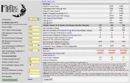
Yes, it appears to be the same. See the voltage limit of 250V. When dealing with high voltage you should be plugging your numbers into what's called a string calculator. I use this one.
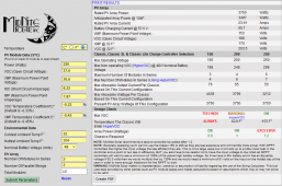
Plugging your panel specs into calculator, this is what you get. Remember that voltage goes up when the temperature goes down. What are your winter lows like? At the freezing point, even the Vmp exceeds the 250V limit at 272V. The Voc is really high, at ~326V.
1627484870624.png

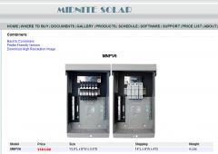
A better option for you might be to rewire your panel strings to 5S3P. With this wiring scheme, you'll be putting 65A into the batteries, well with the 120A limit of your controller. Keep in mind that when you utilize more than two parallel strings of panels, you MUST have a fuse/breaker to protect each string. I use this Midnight combiner. Midnight also makes a cheaper three breaker combiner.
1627485427275.png
1627485157648.png
 
Now you have to enter troubeshooting mode. What I would do first, is a complete shutdown, including physically disconnecting the batteries from the inverter. Disconnect the AC connection first, then disconnect the solar, then disconnect the batteries.

After the unit has been stone-cold for several minutes, first reconnect the battery ONLY. Allow the unit to boot up on battery power only. The display should say something like battery voltage being somewhere around 48-50. If the unit boots, that's a good sign. If not, the unit might be fried.

If the inverter boots normally, and you see battery voltage, try to connect solar. Just one panel most likely will NOT work. A 50V battery will not charge with a 30V solar input. Two panels in series should be 60V, so that might be enough to get charging, but three will be 90Vmp, and be high enough to charge a 48V battery under any conditions. If you feed the inverter 90V, it should tell you if it is charging the battery. The battery voltage should shoot up from the base of ~49V to the charging voltage, maybe 50-55V, depending on battery discharge.

If the battery starts to charge, I'd give it a few hours to bring up the charge level, then try to re-connect the AC breaker. Put a 120V load on the unit like a lamp with a 100W light bulb to start. If nothing goes wrong, try incrementally increasing the load with larger wattage items, up to say 1000W (toaster). If the inverter does not have a problem at this point, I'd say you got lucky.

If the inverter is not performing as expected, you'll need to get hold of company tech support. Most likely this will NOT be a warranty repair/replacement because you abused the unit with too high a voltage.
 
I had it wrong from the beginning in the way they hooked him up some thing about two together equaling eight pairs or something like that I am on the tail end of it because I don’t understand most of it it’s all Greek to me ?‍♀️
The men figured the voltage and I believe it was 34v+ 34v = 68v.
All I’ve ever had experience with is watts, so it’s been difficult to keep it straight…
slow but sure wins the race.
I don’t believe anything is damaged because, to keep it running we have had to stay under 400w, until our solar friend has the time to get back with us. Also I turn the unit off at night to save the batteries because when the batteries get a little bit low the whole thing shuts down for a whole day before it will come back ?‍♀️?.
Patience is a virtue, if I hadn’t learned it before, I’ve learned it now?
Now you have to enter troubeshooting mode. What I would do first, is a complete shutdown, including physically disconnecting the batteries from the inverter. Disconnect the AC connection first, then disconnect the solar, then disconnect the batteries.

After the unit has been stone-cold for several minutes, first reconnect the battery ONLY. Allow the unit to boot up on battery power only. The display should say something like battery voltage being somewhere around 48-50. If the unit boots, that's a good sign. If not, the unit might be fried.

If the inverter boots normally, and you see battery voltage, try to connect solar. Just one panel most likely will NOT work. A 50V battery will not charge with a 30V solar input. Two panels in series should be 60V, so that might be enough to get charging, but three will be 90Vmp, and be high enough to charge a 48V battery under any conditions. If you feed the inverter 90V, it should tell you if it is charging the battery. The battery voltage should shoot up from the base of ~49V to the charging voltage, maybe 50-55V, depending on battery discharge.

If the battery starts to charge, I'd give it a few hours to bring up the charge level, then try to re-connect the AC breaker. Put a 120V load on the unit like a lamp with a 100W light bulb to start. If nothing goes wrong, try incrementally increasing the load with larger wattage items, up to say 1000W (toaster). If the inverter does not have a problem at this point, I'd say you got lucky.

If the inverter is not performing as expected, you'll need to get hold of company tech support. Most likely this will NOT be a warranty repair/replacement because you abused the unit with too high a voltage.
ok will do
 
If you think in watts, just remember that watts = amps X volts. Two amps at 120V is 240watts.

The conventional way of expressing your panel wiring would be 2S8P. That is eight parallel strings of two panels in series. That's OK, but I don't really think it's that optimal. Is each parallel string protected with a fuse or breaker? If not, I believe that could be a rather serious code violation. Whenever you have three or more parallel strings of panels, they are supposed to be fused/breakered.

I think you'd see less voltage drop due to wire resistance if you upped your string voltage. With 16 panels, you might try 4S4P. That is four parallel strings of four panels each. You'd be getting 8A +8A +8A +8A at ~120VDC. That would be 4 12A breakers in the combiner box I illustrated above. You generally select a breaker that is rated for 1.5X the running amperage. Alternatively, you could do 3S5P, or 5S3P, though you'd need to set aside one panel.

There are two opposing forces at work here. In general, you want to get voltage as high as possible to reduce wire resistance to a minimum. There are resistance calculators to determine exactly what your voltage drop will be at a certain voltage with a certain wire. Here's one.

The opposing issue is that the inverter works a little harder to transform higher voltage down to battery voltage. This is a curve that is usually published by the manufacturer. I don't know if Mpp publishes one. In your case, the sweet spot for voltage might be somewhere around the middle of whatever your unit's minimum and and maximum voltages are. I'd guestimate that might be somewhere around 90-120VDC. You should dive deeply into your owners manual to answer those questions, but I'd say you are likely to get best performance somewhere between 3S5P and 5S3P.

I'd carefully read through the manual again and see if you spot a recommended optimal voltage. Then you wire your panels in the scheme that gives you that voltage.
You help is Much appreciated?
I bougot 4 more of the same batteries today, I just have to have more storage if I’m ever to have a fridge again?
 
It would have been better to start over, with higher Ah batteries. Four parallel strings are not optimal, but you have to work with what you got. What I would highly recommend is that you bring each and every string up to the same state of charge BEFORE you parallel them. This might take only 1-2 days.

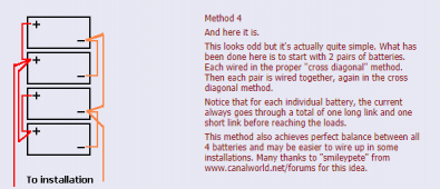
Please pay close attention to the diagrams on the proper wiring of parallel battery strings. Even some well-meaning battery sites get that one wrong. Here is a link to a proper parallel connection.
Method 4 is the best configuration, that minimizes string to string variance. In the pic, they are showing four parallel 12V batteries. In your case, you just need to replace this image in your mind with the four strings of 24V batteries. The wiring will be the same.
1627659769365.png
You have way more panels than necessary to keep these batteries charged, but you will need a good way to monitor what is actually happening. You actually need 100ah X 4 strings X 25Vcharging X 0.125C X 1.175FF = 1472W of panels, so 4000W is far more than necessary. Do these batteries have screw-caps for each cell? If so, invest in a battery hydrometer like this one.
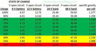
It's the gold standard to measuring a battery's true capacity. Note that it has a temperature correction bulb. The specific gravity of the acid changes with temperature, so you need to take the temperature of the acid into account to get the best readings. Here is a link to a specific gravity chart.
1627660515566.jpeg
Assuming your batteries are 100Ah and you have four strings of them at 24V, then you have 100Ah X 4 strings X 24V =9600Wh of power. Assuming you never want to deplete the batteries past 50%, that gives you 4800Wh of power, or 4.8kWh. At my own cabin, I consume ~2.5-3.0 kWh of power per day just with lights, TV, and the frig running 24/7. If your consumption is equivelent, I'd expect a battery of your size to last you up to two days before getting to 50%. But, that assumes you are starting out with a FULLY charged battery.

That's going to be YOUR job. You'll need to monitor the voltage and SG closely till you get your system optimized. You may need to get into the unit settings and tweek the charge settings to get them optimized for your battery. Forget about the installer coming every day to perform tweeks on your system. Judging how your system was put together, I don't think your installer was the most qualified person you could have selected. So, you're just going to have to step in and make sure that it gets done right. Keep asking questions, and we all can try to help.
 
Back
Top