diy solar

diy solar

Help with cabin setup (48v/280ah/9x325w with Victron Easysolar)

BigVT

New Member
Joined
Jan 19, 2020
Messages
54
First of all, this forum is amazing and I've spent almost every free moment I've had over the last weeks to absorb as much knowledge as possible. I was leaning towards posting this in the Beginners Corner - please move it if that's where this belongs!

I still feel I might be in a bit over my head and need help with how to properly build an offgrid system for a small cabin in northern Sweden. I will be getting professional help from a friend who is an electrician but he's not overly familiar with offgrid systems.

What it will power
Mostly lights and a fridge, but also occasionally some appliances such as coffee machine and power tools. I also want to run a 4G router at all times (which will be used so I can monitor the system through the Victron Remote Management portal), but I don't want to power it through the inverter and suffer the 25w idle consumption when I'm not there.

My setup


setup.jpeg

I've bought everything but the solar panels, wires and circuit breakers already.

Questions
  1. Does this look alright?
  2. Does a 63A circuit breaker type C make sense to the battery? I've understood Type C can handle temporarily higher loads.
    1. I have AWG 5 (16mm2) wires and don't really want to buy larger unless I have to. Do I?
  3. Does the programmable relay setup with the router make sense?
 
1. It looks great. Nice diagram.
2. The breaker as far as i can tell is rated 133vdc. I did not download the specifications and this is the only dc voltage reference i found in the ratings from Schneider. A continuous rated breaker is a good thing.

The current value (50A charger output) may be almost heavy for #5 its right there.... 63A is high by our standard ampacity guides. 90°C or better insulation at least. I would go to your next larger wire size or downsize the breaker to the closest value to 50A (53?) which could avoid nuisance tripping.

If the wire ampacity checked out on your end, disregard that part. I did not go to far out of my way to translate to metric wire.

The values are a bit tight. Continuous rated breakers go a long way to avoid nuisance tripping, but 15A would be certain. 15A maximum series fuse rating from Astronergy.

3. If your poe power supply has no lvd ot will need it and that works.

Open circuit voltage is high if the victron has a do not exceed of 150V. This should be checked.

Great input, thanks!

2. Yes, but the 63A breaker will only deal with the 48v battery pack. That should be OK I assume? You're right, I might be better increasing wire size and next is about AWG 2 (35mm2). 16mm2 seems OK but rather safe than sorry.

Re 10/15A fuses; each mc4 pair can take 30a according to Victron so my thinking was that 3x10 will ensure that. If I go with 15, and add a third series, I should probably add a 30a breaker after the 3x15 - right?

Goodness, does the inverter have seperate cables?

Everything is connected in the Easysolar so it's only one pair of wires from it to the battery.
 
Your inverter if 3000w 48v requires #6 minimum. It will be best to not call for its surge and keep it under 3kW most of the time. Many time its the case where the inverter wouldnt be called for full power output. With a low battery and high demand it might trip. The #5 may work out, #4 better. 63A is tight. It will work.

The numbers work, but just.... inverter overcurrent protection would enjoy being rated about 125% of the useful load, even continuous rated breakers.

The panels cannot output enough power to trip a pv breaker usually. The place to break that circuit for overcurrent protection again would be where the strings combine. So the tens could work and if the wire is ok with it..... 30A on #9-ish, nothing should melt as long as the controller does not call for pv overcurrent to be 30A leave it out.

None of the strings could output much more than 10A (cold and bright) and the breakers basically serve to stop power from shunting back across their conductors in excess of the wire ampacity there. If its all the same size wire to the controller......

One of the things i try not to do here is step on peoples plans or treat them like children....
You obviously poured over the material and kept it tight!

A little room in the wire and overcurrent values is a good thing, it rarely protects the equipment. Charge control/inverter breakers can and should have a maximum allowable overcurrent protection spec.
 
Last edited:
Re 10/15A fuses; each mc4 pair can take 30a according to Victron so my thinking was that 3x10 will ensure that. If I go with 15, and add a third series, I should probably add a 30a breaker after the 3x15 - right?


Everything is connected in the Easysolar so it's only one pair of wires from it to the battery.

Yes on the fourth breaker 30A.

#4 (70A-85A) is ok #2 (95A-115A) would be great. No need for larger if you will not allow high surge demands. It wont zorch, it will trip breakers though. They shouldnt be relied on for repeatedly limiting current where a larger wire and breaker would be appropriate. Its what they do, but not a good practice.

Im sure the manual has a guide for their dc line to the unit. I use them if available. If not, sizing continuous rated breakers and conductors 125% of max load is a good baseline.
 
I really appreciate the constructive feedback - and for what it's worth I'd much rather be treated as a kid online by people that know a lot more than have my house burn down...

Got it. So I'll change to #2 then and a 100 amp fuse (I got one of these marine ones I can use). The inverter is max 6000w so that will also cover some peak too.

The only reason I want individual fuses on the strings is that I've understood that if I do connect a third series and and one breaks, things can get nasty if the other two strings pour their current into the broken one. I'll upgrade to 3x15 and 1x30 then.

Right - panel voltage in low temperature. It can get to -30 in the winter at most, although thats unlikely and I will not be charging the lifepo4 batteries below 2c - but I guess this restriction applies in all instances unless I physically disconnect the panels?

Temp coefficient for voltage on panel is -0.4. So If i got this right that's 55 less than +25, and 55x0.4 = 22%.

So 3x325w panel with open circuit volt of 45.67 becomes 3x45.67x1.22 = 167 so that's a no go.

If I get the 275w version instead that's 38.45x3x1.22 = 140.7 which works.

Or I go with the 325w panel, but 2 in series and 5 in paralell (10 total). 2x45.67x1.22 = 111. Any downsides of this approach? Heard batteries might not start to charge as early. I'll have to read up on this.
 
Last edited:
Thought I'd update this for anyone interested. Big thanks to everyone on the forum - It would definitely not have been possible without the knowledge I found here. Any input is still greatly appreciated (bash away so I can improve it!)

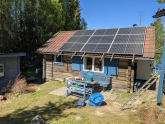
Installed the system above but with 9x335w mono panels from Astron Solar, 3x150cm grounding rods and I haven't programmed the low voltage disconnect for router but it's drawing a few watts from a 14kw battery bank so I'll see if I ever do that... Panels are all facing east but I still have 3 left that I intend to mount south/southwest later on. It's currently way oversized (see graphs below) as I'm only using a 80x60cm fridge, led lights and some power tools, but I got a water heater I intend to use a dump load and program the inverter to only power it when battery is above set SOC or voltage, and will add more stuff in the future. In fact, even when I have no direct solar the panels are still almost producing more power than I use.

Just getting the mounting system correctly installed and making sure the hooks wasn't putting any weight on the tiles under them was the real PITA and we had to use the angle grinder on most of those tiles to get it perfect.

Been experimenting with the battery voltage, and currently running it at 54.1 with absorption for one hour and float at 52.8 - which according to my BMV712 battery monitor keeps the battery between 70-60%.


---

Some images (I just now realized I didn't take much images of when it was all complete so some wiring looks a bit messy)

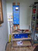
Victron Easysolar, battery and fuses for each string (battery fuse not installed in image). I made a hole for the wires and put the BMS on the shelf above the cells. The included balancing wires was painfully short for a pack of this size, maybe I'll fix that later.
1593468313536.png

Solar panels mounted with Van Der Valk system (had intended to put up 3 more panels, but time ran out and I realized I didn't need them yet)
1593468572914.png

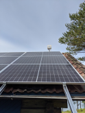
Router / Access point installed inside case with directional antenna, powered through PoE (and cable is not yet strapped properly in this image - but nothing touches the roof)
1593468482647.png


Some data from Victron VRM

1593466185976.png


1593466572613.png


1593466667529.png


1593467296544.png


1593467305844.png


1593467379875.png
 
Back
Top