diy solar

diy solar

Help with Ground Mounted Solar

kwmivp

New Member
Joined
Mar 1, 2023
Messages
5
Location
Washington
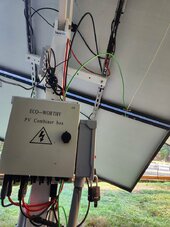
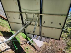
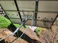
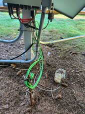
I have tried hiring multiple Electrical contractors independent and through companies, all are booked out, too busy. I have installed these myself and one of them said there are numerous issues here and was told that the ground rods are in the way and not low enough in the ground. I just would like to get this done and inspected. Yes, I know there needs to be stickers on the pipes, I have them, just waiting for a dry day. These plug into a hybrid inverter that has RSD (Rapid Shut Down) and I have a blade cutoff switch before the wires go underground in Sch40 to the base of the shop (in Sch40 strapped to the base of the wood siding) and around to the back of the shop where they go in, and transition to metal LB and Flexible metal conduit to the inside of the inverters. What things can I do a better job on or change to pass inspection (Wa State).
Sorry the concrete bases are a mess because the chickens decided it looked better that way.


20240319_110418.jpg20240319_110428.jpgLeft.jpgFar Left.jpg
 
Last edited:
typicaly there not not going to want to see that much ground rod above the ground. There also not going to want to see conduit suspended like it is above the ground..there may even be a spec for how far underground it needs to be.
 
Sorry, I can't help with your installation, but what kind of wind speeds do you see at your location? Those panels would be flying away or torn apart where I live. You might have a look at windy.com
 
FWIW, and my understanding:

Conduit needs to be 18" underground for PVC. I think metal can be less, but not 100%.

Ground needs to run in the conduit to the inverter, with the PV wire. Grounding at the PV is not enough, nor even required.

It looks like you have the 6 gauge wire required, which is good. You do not need to run 6 in the conduit.

I'm not sure you can use MC4 connectors to the combiner. I may be wrong on that, but I am fairly sure you can't have them going into the shutoff.

All based on my limited knowledge.
 
typicaly there not not going to want to see that much ground rod above the ground. There also not going to want to see conduit suspended like it is above the ground..there may even be a spec for how far underground it needs to be.
It is above ground as there are Power mains running from the street in the area, and I do not want to be digging near there, additionally if it needs to be dug up, repaired, these conduits are removable. Inspector actually commented that if I was going to do it that way I would need to have the channel strut (in the middle) strapped to it with concrete to hold them.
 
Sorry, I can't help with your installation, but what kind of wind speeds do you see at your location? Those panels would be flying away or torn apart where I live. You might have a look at windy.com
Wind never gets above 11mph in the area, too many trees, and buffered by other structures.
 
Oh dear my guy, I don't think any of this can be brought up to inspection passing. It's not that kind of hardware.

I don't get high winds either, but my county still requires an engineered solution for like 100 minimum or something. I think they all do.

Not that I actually get the permits, but if I did, that's what they'd want.

Edit to be more specific: It's your ground mounts I mean, the only way I could see those passing in my county is if you did the engineering for them, but it probably couldn't pass engineering the way that they're built.
 
Last edited:
This can all be overwhelming at first - but stick with it and it will make a lot of sense over time.

Did your inspector give you a written report with all the issues flagged? If not did you take lots of really good notes? You may also be able to get a copy of this report if you didn't get one at the time.

They typically will NOT tell you how to do things and that can put them on the hook for the design flaws. But they will tell you which sections of the NEC you violate. You can get free access to the NEC from a sticky in the main forum.

Energy audit? what are you trying to power?
Are you going grid tied or off grid?
Are you doing battery bank or just when the sun shines?
Are you going to back-feed the grid or be net-zero?
Equipment list? For inspections typically everything needs to be UL listed down to the crimps on your wires.

From the pictures and all my studying on this forum you would have to start by taking apart all your wiring and boxes and connections and start over before you could be code compliant.

First - you need a well drawn plan that is what the call a single line design. Basically instead of showing the individual conductors you show the groups and where they connect to and from. There are a variety of programs, but draw.io is free and many people use it. You may end up with a bunch of drawings for different aspects of your install, but if you do grid tie they will usually require that.

Second - if you need to pass inspection you need to know the rules. So, find out what version of the NEC your county uses and also the state and get the correct version of this book - I suspect you will find it is the NEC2020 version but check first. Then you can lookup stuff and see what the book says and also come here are ask questions.


For free check this resource out and see what applies to you - pay particular attention to page 15

And poke through the resources section at the top for examples of drawings and everything else you might need.

Generally trades people will not even bid on or look at a job like this because it will take them a day to figure out what is there are where to start. Not worth their time to figure it all out and bid then be turned down because the price is high. Not saying this is your case. So if you want someone to do the work for you, you will have to provide them with clean plans of what you have so they can just look at it.

One tip - ground rods can only have 6" exposed and they can not be cut off if they get hard to drive. Another tip is where ever your inverter is there should be a ground wire attached. If the inverter is the only source of power then it will have a ground rod or a pair of rods 8ft apart, but connected by a single unbroken wire to the inverter so rod-rod-inverter, everything else is attached to this single ground to prevent shock hazards. This wire is generally #6 but check the code book for your area.

If it is grid tied it will have a ground to the main panel. In any case the wires to your panels should also include an extra ground wire that attaches to anything metal out there. There should NOT be a ground rod at each panel mount or you will have ground loops and it will cause you major issue.

Typically RSD are not required unless you are doing roof mount. That is unless the county or state you are in requires them for every install.

Another thing is if you leave the wiring and everything above ground at the panel mount site it usually requires a fence around it to keep people from the potentially dangerous voltages. I am not telling you to build I fence, I am telling you to check your local code or the NEC whichever is more strict.

An last but not least, don't be afraid to ask questions - especially if you don't understand an answer or WHY something is done the way it is.
Wow! Thank you so much for your response, time and patience! Let me digest this all.


I will try to cover everything.

1yr ago this project is to ONLY power my detached shop (70' from house), where my home office, freezers, fridges, etc, are, in case of lengthy power outages. We do have power out a few times a year, 2 in the last week. This project was to keep me out of trouble, and I wanted to learn, so when it has issues.... Yea, Im that guy :)

Energy audit? -No
What are you trying to power? -Shop only
Are you going grid tied or off grid? -For now, just shop, then maybe power the house, but not selling it, no net metering.
Are you doing battery bank or just when the sun shines? -Yes
Are you going to back-feed the grid or be net-zero? -No, just want self-sufficiency.
Equipment list? -Yep, got that, details below.

For inspections typically everything needs to be UL listed down to the crimps on your wires. -Well that's going to be fun!

Inspector
I had the inspector out back in Sept, to approve covering the Sch40 buried between the cutoff switch at the array, and the side of the shop. He approved that. The rest he would need way more time to review, and he wants to do all of it end to end (Solar panel to electrical panel).

Inverters
I now have (at rear of shop) 2 EG4 18kpv in parallel (mounted on 1/2" ply topped with Hardie Backer). AC Power output via flex metal conduit going to 4x4 boxes to a Siemens 125 amp panel with 2 50amp breakers. That feeds into a 3-3-3-5 copper Ser cable into the attic floor (Tacked to 2x4s buffered by lateral 2x4s to block insulation), down into the 125 amp C-Hammer sub panel (at front of shop) to a 100amp breaker with an interlock to the 60 amp from the house.

Batteries
There are 9 48v LFP (15cell) battery bank and a dual 48v FLA extreme deep cycle battery banks (8*6v). (hence the DC switch)

Gen
A grounded, and Zombie Boxed 9500 Predator Generator (W Neutral clipped from gnd) connected via the L14-30 (4 wire, W/ appropriate sticker) connected to the Gen Inputs. Inverter controls load to 5.5kw total.

Grounds
For the inverters there is a ground rod just on the other side of the wall (Back of the shop) as well as connected to the Shop Sub panel ground via the Ser cable.

Ground for the Array, I was just told yesterday, needed to be #4 bare copper.... So, redo.....and yes agreed, those rods are way too high.
BUT, if I only need to have 2 (8' apart) and I put those over by the tracker that has the combiner and blade cut off switch. If #4 wire is true, then I will redo all that.

RSD
It was just part of the package, but eventually there will be panels put on top of the roof of the shop, and on the South Facing wall, I just need to get what I have so far signed off on.

Plans
As for plans, I have multiple Visio diagrams of 1 and 3 wire plans for Overall, the solar side, and Post Inverters AC side. I also have the 3 wire plans from EG4 for my use case (off grid plan fits best for my scenario).

Quandaries
Conduit watertight?
I was also told that the Conduit that goes between the trackers would need to be watertight coupled, meaning I would have to pull ALL the wires and redo all of them. Well, while I'm redoing all the ground rods and wires......

Conduit DC power cables???
An electrician told me the 2/0 marine (Gregs Marine) tinned wires going between banks, battery bank switch, busbars and inverters are hanging loose and need to be in boxes (for the busbars and switch) and conduit (The liquid tight flexible gray kind) That I am stumped on, as its NOT that flexible! And I have contacted Inverter supply, and other stores on a solution, but there are none, and no one is calling for DC Breaker boxes with Busbars. There are a couple out there, but they are made for specific inverters.

I also know that the main 200 amp panel in the house would need to be replaced with a 400amp, and an auto transfer switch put in, but those are another chunk I am not ready for at this point.

I have tons of Pics for all of this, let me know.

I will read over the mentioned material, thank you for that!

Ok, I need to go do dinner, parent and chill.
 
Last edited:
How do you eat an elephant? One bite at a time, with hot sauce. Tastes like chicken.

Either make this you build thread or start a build thread titled "kwmivp's build thread".... in that thread post everything you got that you want help with. I would suggest post your plans and diagrams first, then start with one section at a time, post pictures and ask about that section.

A couple of more pointers. All PV wires inside a structure are required to be in metal conduit. That metal conduit must be connected to ground for your main electrical panel. For the whole system there can be one and only one ground rod. The inspector may require 2 rods 8ft apart connected to you main panel. There shall not be any other ground rods used. The idea is the whole system is at the same potential. The system ground are supposed to be as close as practical to the service entrance where the wire from the grid enter.

We are talking on this topic currently

So, unless your ground rods next to your panels are part of that ground system for the main panel you may as well abandon them. They will cause issues and kill equipment if lightning strikes nearby.

So, for your panels you run wires through buried conduit, the grey plastic stuff. Assuming you are connecting dc to the panels you would run pv rire for pos and negative and an extra wire to use as ground out there. That wire would be tied to any metal bits like the panel frames, metal boxes etc. But it would NOT be tied to any sort of ground rod out there. If you want to use them you put a chainlink fence around your array and ground that to the rods. But you don't attach the fence to the panels or ground wire.

No matter what you do, it needs to be neat and orderly. That is in the code

Takes a while to wrap your brain around it all.
 
Last edited:
1. You need to drive that ground rod down until only 6" is showing.

2. Multiple ground rods can cause ground loop issues.

3. Ground wires should be as straight as possible for the best protection from lightning. I'd get rid of all those wire loops at the ground rod.

4. The conduits from the left and right with the sweep 90°'s should be flipped over so the openings face the ground and don't allow water to run into them.

5. All of the conduit and fittings you use should be listed for use in wet locations. Set-screw conduit fittings are for indoor installations. For wet conditions you should use compression-type fittings.

6. Proper conduit clamps should be used to secure the conduits to the posts. A U-bolt is prone to crushing the conduit when tightened.

7. It looks like a tracker is controlling the panel array. For the 2nd picture - if your ground wire is solid copper it is going to fatigue and break if it is not properly mechanically supported at the panel connection point.

8. General wiring housekeeping, making sure it is all neat and secured properly, goes a long way towards having a long lasting installation. Also - 1st impressions from an inspector are set when they walk up and see the project. If it is sloppy it may meet code but it will likely encourage extra scrutiny.
 
In my area exposed conduit where it comes out the ground needs to be metal of sch 80 extra heavy conduit. It also needs to be equipped with the capability of vertical movement as soil elevation will vary slightly over the course of a year. I believe they are called conduit expansion fittings.
 
Conduit DC power cables???
An electrician told me the 2/0 marine (Gregs Marine) tinned wires going between banks, battery bank switch, busbars and inverters are hanging loose and need to be in boxes (for the busbars and switch) and conduit (The liquid tight flexible gray kind) That I am stumped on, as its NOT that flexible! And I have contacted Inverter supply, and other stores on a solution, but there are none, and no one is calling for DC Breaker boxes with Busbars. There are a couple out there, but they are made for specific inverters.

The only reason to use tinned marine wire between battery would be if they were outside or built in a coastal area.

Even then I would probably use a good grade of welding wire crimp the ends to they cold weld ( hydraulic crimper) and put heatshrink with the glue on the inside. Tinned lugs.
 
Back
Top