I appreciate your time. I'll try to keep this quick. I keep coming back to this paragraph from
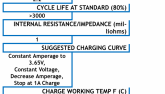
here when researching how to charge lithium batteries. "During the conventional lithium ion charging process, a conventional Li-ion Battery containing lithium iron phosphate (LiFePO4) needs two steps to be fully charged: step 1 uses constant current (CC) to reach about 60% State of Charge (SOC); step 2 takes place when charge voltage reaches 3.65V per cell, which is the upper limit of effective charging voltage. Turning from constant current (CC) to constant voltage (CV) means that the charge current is limited by what the battery will accept at that voltage, so the charging current tapers down asymptotically, just as a capacitor charged through a resistor will reach the final voltage asymptotically."
I think I can achieve this with this charger by setting the bulk charge to 26.2 (70% SOC?) followed by a float charge of 29.2. Hear me out. I've watched it charge, and as it approaches that "float" voltage, it decreases the amps flowing to the battery "asymptotically" as mentioned above. TicTag mentioned that "permanently maintaining the battery at 29.2V will damage it." But this is an off grid solar system the battery will cycle every night. Will floating for a few hours per day be a problem? 29.2 is not a number I am committed to at all. It's just a placeholder for conversation purposes.