diy solar

diy solar

Help with wiring schematic for 24v vehicle mounted system.

Hive9

New Member
Joined
Dec 26, 2020
Messages
4
B7B833BC-DDA3-4200-ACA0-5B18D844B3B1.jpeg
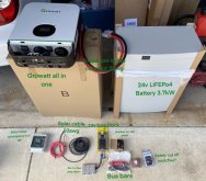
Does anyone on here do wiring diagrams for someone like me who has already accumulated several parts for their systems?
I’ve got 3 435W panels already mounted and wired in parallel to feed the Growatt & 24V battery. This is to power both 12V fuse block and 120V breaker panel. I have a generator for back up power but I have no intention of charging from the vehicle alternator. Every schematic I’ve found so far has alternator charging or grid tie that isn’t applicable for me.
Thanks for any advice given!
 
So you want to charge from the Generator and from the Batteries? Have you got the system set up with the panels yet?

I'm pretty new so probably can't be much help. But it def helped me out to just put all my components onto a page and start drawing lines between them. Even paper would be ok, I've seen some people post pictures of just paper.

Looks like chmiko is setting up a similar system over on this thread.

 
I’m good with everything until I get to AC out...... I need to know what that wiring looks like to go from the Growatt to the breaker panel and the 12v fuse box and if there should be anything in between?
 
AC out won't have anything to do with the 12V fuse box. The 12V fuse box will be connected to the 24V/12V DC-DC converter which will be connected to the main positive and negative DC busbars. You'll want a fuse between the positive busbar and the DC-DC converter.

The AC out will go straight to the AC breaker panel with the hot wire going to the main breaker.
 
Back
Top