diy solar

diy solar

Hot points at anl fuses

Kcdaniels

New Member
Joined
Sep 22, 2019
Messages
263
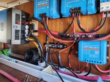
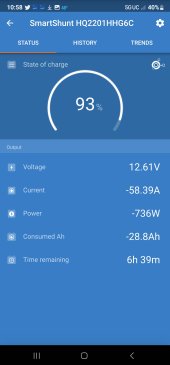
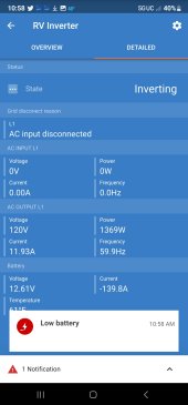
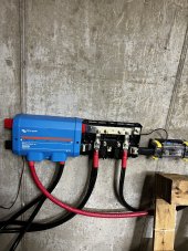
My system is 12v two Lithium batteries Wired in parallel For a total of 400 amp hours Connected to a victron multiple plus 2000 inverter.

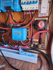
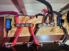
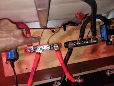
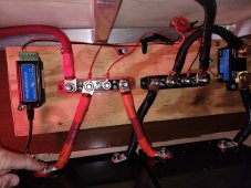
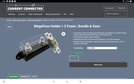
I just upgraded my wiring from 1/0 to 3/0. I'm using 200 amp anl fuse right before the inverter and another 200amp anl fuse right before the battery cut off switch..

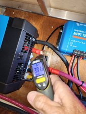
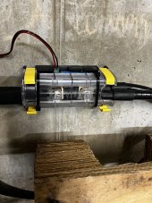
After rewiring to the upgraded 3/0 and running a 1300 watt load for about 10 minutes the only areas of heat are right at both fuse points..

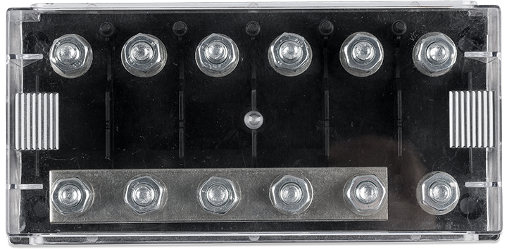
Would it be a better option to up grade these fuses to a t class fuse ? And if so what would be a recommendation for a brand ?

The pictures are before the upgrade to 3/0 wire
 

Attachments

  • 20230112_131838.jpg
    20230112_131838.jpg
    355.2 KB · Views: 33
more pictures
 

Attachments

  • 20230112_131831.jpg
    20230112_131831.jpg
    223.5 KB · Views: 39
  • 20230113_150710.jpg
    20230113_150710.jpg
    317 KB · Views: 38
How hot? Hotter than before you switched over?

What is the voltage drop across the fuses?
Well I didn't have my temp gage with me but got hot enough when finger held for about 5 seconds? all other areas of wire were barely warm.
Will have to go back to the trailer to measure voltage drop...trailer is at storage
 
Well I didn't have my temp gage with me but got hot enough when finger held for about 5 seconds? all other areas of wire were barely warm.
Will have to go back to the trailer to measure voltage drop...trailer is at storage
Voltage drop = heat

For example .3 volts x 100 amps = 30 watts of heat concentrated in that one spot. Might be a problem, might not be.

Take the system back up to that 1300 watts and then get the total voltage drop from bat neg to inv neg. Same for positive and then look across every connection.

In my experience fuses have less voltage drop than breakers. If there's much difference between ANL and Class T I haven't noticed. Others may be able to speak to that.
Thank you for the help...heading out to the trailer now..will post results..
 
Looks like one battery runs through the shunt but the other doesn't. I had heat from my ANL fuses when I pulled a heavy current, I've since changed over to MRBF on the battery terminal (no heat now).
 
ok ran up to close to 1400 watts..
temp cool all areas except at fuse area
voltage at batteries was 12.68 v ..fuse at battery cutoff was 12 .47..
fuse at inverter was 12.02

temps at all areas except fuse areas was cool to touch..
fuse at battery cutoff was around 200 degrees Fahrenheit.
fuse at inverter was 381 !!
also noticed that inverter made more noise at 400 watts than it did at almost 1400 watts is that normal ?

all connections recheck and tight...I think it's the cheap fuses ?

measurements were made after about 20 minutes or so running load
 

Attachments

  • 20230115_103225.jpg
    20230115_103225.jpg
    179.8 KB · Views: 22
also shunt is showing less draw than inverter shows ? is that normal
 

Attachments

  • Screenshot_20230115_105854.jpg
    Screenshot_20230115_105854.jpg
    105.4 KB · Views: 4
  • Screenshot_20230115_105835.jpg
    Screenshot_20230115_105835.jpg
    129.1 KB · Views: 4
Looks like one battery runs through the shunt but the other doesn't. I had heat from my ANL fuses when I pulled a heavy current, I've since changed over to MRBF on the battery terminal (no heat now).
should the positive wire of shunt be connected to positive of first battery instead of the positive of buss bar ?
 

Attachments

  • 20230115_114358.jpg
    20230115_114358.jpg
    274.9 KB · Views: 18
  • 20230115_114408.jpg
    20230115_114408.jpg
    272.6 KB · Views: 16
The positive wire for the shunt can be either, but I like the buss bar location. Your shunt is only measuring what is coming out of the battery on the right. The battery on the left is connected to the negative buss bar and bypasses the shunt. Assuming the batteries are balance, the shunt would read half of what the inverter is using.

My ANL fuses were the cheap ones. Just looking at the fuse element and considering 100A flowing through it, I can imagine some heat.
what would be the correct connection...what should I move ?
 
The negative from the left battery needs to move from buss bar to the bottom terminal of the shunt. Looks like it will need a longer wire. Note that the negative from the right battery should be the same length as needed for the left battery to keep things balanced.
 
The negative from the left battery needs to move from buss bar to the bottom terminal of the shunt. Looks like it will need a longer wire. Note that the negative from the right battery should be the same length as needed for the left battery to keep things balanced.
Ok think I understand... Will change left battery negative to the negative of the shunt...which would be the same as where I have the negative from battery to shunt then on the load side of shunt connect to negative buss bar??
Also would these fuses be a better choice ?
 

Attachments

  • Screenshot_20230115-131614.png
    Screenshot_20230115-131614.png
    453 KB · Views: 16
Ok think I understand... Will change left battery negative to the negative of the shunt...which would be the same as where I have the negative from battery to shunt then on the load side of shunt connect to negative buss bar??
Also would these fuses be a better choice ?
I used Victron mega fuses 48v 300amp. All negative connections need to go through the shunt. Class T would be more appropriate actually. You can see on my photos two 4/0 negatives from the inverter stacked on one side of the shunt on the other side of the shunt is a short flexible bus bar attached to the negative side of my main bus bar. So everything on the negative flows through the shunt. I also have the shunt power on the positive bus.
 

Attachments

  • 0612D477-DD83-4891-ABF5-64F1730F0E5F.jpeg
    0612D477-DD83-4891-ABF5-64F1730F0E5F.jpeg
    1.2 MB · Views: 22
  • B0C66CEB-95E7-47F0-9FF0-34E43EDCBFD3.jpeg
    B0C66CEB-95E7-47F0-9FF0-34E43EDCBFD3.jpeg
    1.5 MB · Views: 22
Last edited by a moderator:
You fusing concept is incorrect . The fuses need to be as close as practical to the batteries and to a distribution buss bar.
The fuse protects the cable and anything on the end of the cable.
A fuse is needed in the feed to each MPPT controller, AC charger or load.
A MRBF fuse is OK for lithium at 12 volts for the main battery fuse. Class T is better with a higher withstand current at 20 k amps. MRBF is 10k amps. MEGA are only 2k amps rated, this is OK for distribution within the system but too low for a main battery fuse.
Consider MRBF with BlueSea holders directly on the battery positive.

The heating effect you are experiecing may be due to poor contact and/or low quality fuse and/holders.

For distribution fuses the Victron Lynx power in incorporate buss bars and fuse holders.


Or fuse holders,

Mike
I agree class T fuses are better. I used modified Victron Power Ins to fuse each battery despite the fact that each battery has a 200a breaker and the Sol Ark has breakers on each battery lead.
 
Back
Top