diy solar

diy solar

How about a solar generator repair?

Supervstech

Administrator
Staff member
Moderator
Joined
Sep 21, 2019
Messages
11,550
Location
Belmont, NC
Ok, I picked up a dead rockpals 250W SG...
LOOKS COMPLETELY NEW, ZERO WEAR ON ANY SURFACE...
I mean no wear on anything.
I open it up, and the battery is sitting at 10.6 so, shipping voltage.
I dig into the bms, and it is an all in one board. Bms, usb, and inverter all on one board.
Nothing burned or bulged...
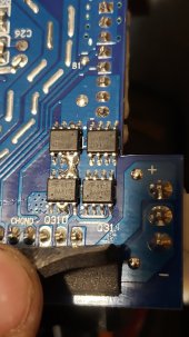
I start examining everything closely and find this...
It looks like poor soldering on the little processors.
Anybody know if that is normal?
I figure I will soak some Flux in there, suck out the blobs and see if it works...
I'm tempted to buy another one just to open it up and see if they are supposed to be blobs there.
 

Attachments

  • 20210422_185844.jpg
    20210422_185844.jpg
    115.2 KB · Views: 45
Given it looks like a parallel circuit to the chips on the right, wicking those solder blobs off might do the trick.
Can't wait to see how this goes (one of the youtube channels I watch occasionally is TronixsFix)
Rootin for yah!
 
I'm betting you found the problem. How did you obtain this rockpals?
 
My guess is the BMS isn’t functional... and the board is all integrated. Not a clue how to organize this into a diagnostic... oh well.
I got a decent 3S pack of 18650’s 20Ah
 
They are power MOSFET amde by Alpha & Omega
AO4413 (N-Channel), AO4415 (P-Channel).
The solder bridge on the pins do not matter since those pins are connected internally anyway.
They look to be for the BMS charge/discharge output section.
 
Does the bridge across the chips to opposite chips not indicate an issue? The unit does nothing.
I plug in the solar, and the LED’s strobe... like it’s charging, but no voltage change at the battery...
Simply haven’t got a clue how to trace issues.
I am no electronics guru...
Simple mechanic here.
 
Pack is at 10.9 actually, nearly 11V but no increase... and no idea where to check for an issue.
 
Does the bridge across the chips to opposite chips not indicate an issue? The unit does nothing.
I plug in the solar, and the LED’s strobe... like it’s charging, but no voltage change at the battery...
Simply haven’t got a clue how to trace issues.
I am no electronics guru...
Simple mechanic here.
If you look at the traces, those pins of the two chips are connected together already via the trace. You need to check the Voltage between Source pin and the Gate pin of each MOSFET to see if they are bias on or not.
 
Yeah, I have no clue how to do that.
Ya want the board?
I'm going to turn the pack into a spare battery for something else.
The bms leads are odd, looks like 3 main negatives, three mainn positives and two cell traces for cell1 and cell2
 

Attachments

  • 20210423_091146.jpg
    20210423_091146.jpg
    71.3 KB · Views: 3
...Simply haven’t got a clue how to trace issues....
I am no electronics guru...
Simple mechanic here.
Watch some of the TronixFix videos, the guy shows a lot of his tips and tricks. He uses the diode function on his meter a lot to see what transistors are blown.

Seriously, you should try to fix it. It'll be fun for you and the rest of us! ;)
 
Last edited:
Watch some of the TronixFix videos, the guy shows a lot of his tips and tricks. He uses the diode function on his meter a lot to see what transistors are blown.

Seriously, you should try to fix it. It'll be fun for you and the rest of us! ;)
... I suppose I could try... I looked over his videos, he mostly deals with games and phones. Not sure how applicable they will be.
 
... I suppose I could try... I looked over his videos, he mostly deals with games and phones. Not sure how applicable they will be.
You don't really care about the device, disassembly/assembly.... just skip over that and play at 2x speed. What you're looking for is where he pulls out his digital multimeter. He usually talks about what he's doing, what to look for, and why.

Really you just want to know how to find a few bad things (e.g., transistors, diodes, caps)... probably better videos, he's the only one I know about.

I'd start from the battery and work my way forward testing voltages.

With some photos and readings, members might be able to give some feedback.
 
Last edited:
Typically components work or are blown, so they'll have a value, be open, or shorted.
You care about the open/shorted ones rather than trying to read the bands on a resistor to check to see if it matches. If it gets down to that level probably time to trash it.

WARNING: You can test voltage while it's powered up, but make sure it's powered down/disconnected and the caps have drained before testing anything else less you blow your meter.

A lot of stuff is easy... here's a link for basic components (just found it ;-). If your meter has a diode and capacitor tester you should have what you need.

I haven't seen it on TronixsFix, but if you have an IR camera that might be a way to spot problems too.
 
Last edited:
Yeah, I have no clue how to do that.
Ya want the board?
I'm going to turn the pack into a spare battery for something else.
The bms leads are odd, looks like 3 main negatives, three mainn positives and two cell traces for cell1 and cell2
How difficult to ship the unit? You can use power supply to simulate the battery to power the board to see if the display or indicator lights will come on or not, also look for fuses (some of them may be SMD (Surface Mount Device) micro fuse that is hard to see, but you can go by the designator, I.E. F1 will be fuse number 1, you can already see that the MOSFET has Q for designator I.E. Qxxx, Cxxx will be for Capacitor. You can also check Voltage regulator IC's.
 
Last edited:
If you suspect the BMS is "tripped" and preventing current flowing across it, you could try jumpering over it to see if that makes the unit come alive.
 
I suppose I could try.
The board isn’t very clearly defined.
The charging board, and the main board are all one...
I will post some pictures of it all tonight.
 
Back
Top