kenkoh
Solar Enthusiast
Is this safe or how can it be made safer besides grounding? https://bit.ly/38BLlDa
This is for my other bugout cabin.
This is for my other bugout cabin.
You're refering from battery to SCC correct? Initially I used just a fuse, I now put the breaker as an easy disconnect. If you have a reason why not I'll study. Maybe I should make my breaker 75a and the fuse 80a?i do not understand why you put in serie a 60A and a 75A fuse.
Either one or the other, no need/sense for both a breaker and a fuse in the same line. If all the breaker is being used for is a switch, use a real switch.You're refering from battery to SCC correct? Initially I used just a fuse, I now put the breaker as an easy disconnect. If you have a reason why not I'll study. Maybe I should make my breaker 75a and the fuse 80a?
I have no idea what that is.Looks nice.
Will you be putting a pre-charge resistor on your inverter disconnect?
View attachment 7480
Link please? Thank you.Either one or the other, no need/sense for both a breaker and a fuse in the same line. If all the breaker is being used for is a switch, use a real switch.

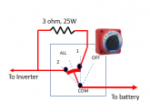
Thank you I'll look into these.This is the pre-charge circuit for the inverter disconnect.
View attachment 7481
I like this switch because you can not go from "OFF" to "2", You must go through 1 first.
https://smile.amazon.com/Perko-8501DP-Marine-Battery-Selector/dp/B00144B6AE/
Or
https://www.ebay.com/itm/Perko-Comp...Switch-Disconnect-1-2-All-8511DP/291384612715
This is the resistor I use:
Resistor: https://smile.amazon.com/gp/product/B07H5GBF2D
This is really helpful, spelling it out step by step I'm slow.With the pre-charge circuit, you can turn the switch to one for a second to pre-charge the capacitors on the inverter, and then turn the inverter full on.
TURN ON:
1)Confirm Inverter Switch is OFF.
2)Turn switch to ‘1’ & count to two.
3) Turn switch to ‘All’
4)Turn ON inverter.
(It does not need to be switched to ‘2’, but it does not hurt if it is.)
TURN OFF:
1)Turn Off Inverter.
2)Turn switch to OFF
Notes:
•The switch can not get to ‘ALL’ or ‘2’ without going through ‘1’
•The pre-charg resistor will be mounted on back of the switch.
•Even if the user does not pause on ‘1’ the inverter capacitors will probably be adequately charged.
With the pre-charge circuit, you can turn the switch to one for a second to pre-charge the capacitors on the inverter, and then turn the inverter full on.
TURN ON:
1)Confirm Inverter Switch is OFF.
2)Turn switch to ‘1’ & count to two.
3) Turn switch to ‘All’
4)Turn ON inverter.
(It does not need to be switched to ‘2’, but it does not hurt if it is.)
TURN OFF:
1)Turn Off Inverter.
2)Turn switch to OFF
Notes:
•The switch can not get to ‘ALL’ or ‘2’ without going through ‘1’
•The pre-charg resistor will be mounted on back of the switch.
•Even if the user does not pause on ‘1’ the inverter capacitors will probably be adequately charged.
Kinda yes. Once the switch is in the Both or 2 position, the voltage across the resister will be nearly zero, so the current through the resistor will be nearly zero. I say 'nearly' because the direct path will have a very small resistance creating a very small voltage.Oh, so the resister circuit and the direct circuit are in parallel and the electricity prefers the path of least resistance.
Got rid of breaker https://bit.ly/3bLablYI made a label for the switch to help make it clear how to use it.
View attachment 7487
Post #8What specs for the resister?
Ok, this may not work in all cases. On my AIMS inverter, the caps don't accept (pre-charge) until it's turned on. When you turn the unit on, THEN the caps charge. Until it turns on, nothing happens. So in your example and config, moving the switch to position 1 will do nothing on my inverter. I would have to:With the pre-charge circuit, you can turn the switch to one for a second to pre-charge the capacitors on the inverter, and then turn the inverter full on.
TURN ON:
1)Confirm Inverter Switch is OFF.
2)Turn switch to ‘1’ & count to two.
3) Turn switch to ‘All’
4)Turn ON inverter.
(It does not need to be switched to ‘2’, but it does not hurt if it is.)
What specs for the resister?
On my AIMS inverter, the caps don't accept (pre-charge) until it's turned on.
Pretty sure. When I get a chance, I'll review it and run a few tests.Are you sure of that? Some of the inverters talk about 'soft start' to minimize current surge, but that is on the output not the input. Every inverter I have used has the on-off switch after the capacitors. (They don't want to deal with the surge either ☹ ).
For a 24 volt system, I would go with a 6 ohm 50watt or a 12 ohm 25W


