diy solar

diy solar

How can I make this 600w Safer?

you can use MOSFET , no contactor, no spark, the same mostfet you use in the inverter.
and only a few miliamps to control them.
for the price of a big switch you can probably align enough MOSFET to get the necessary amps conduction (chinese way to do it)
or get a 500A mosfet.
 
I would combine all 4 panels with a combiner box that way all panels have a breaker or fuse, and if one is shaded the other 3 will still produce power, run 8awg with a 50amp breaker before the scc and a 60 amp between the scc and battery, the midnite breakers flip at a higher than rated amp, so some safety there so even if its dumping 60 amps it wont flip.
 
you can use MOSFET , no contactor, no spark, the same mostfet you use in the inverter.
and only a few miliamps to control them.
for the price of a big switch you can probably align enough MOSFET to get the necessary amps conduction
Yes.... kinda. since we are dealing with fractional volts from charged to discharged, I don't like the voltage drop across mosfett if I have an inverter/charger (It is not as big of a deal with a straight inverter). The other challenge becomes fabrication of the circuit into a reliable unit for installation. The interesting/ironic thing is that the Victron Battery Protect is essentially what you are describing, but they do not support putting the device in line with the inverter.....because of the inrush current. I could probably use the Battery protect as part of a circuit that pre-charges first but it would not be a supported configuration from Victron's perspective. (And it is an expensive solution).


we use that in airsoft gun to get better power control.
because we use relatively small lipo battery to move the coil, so there is big amp involved a sparks make a messy trigger.
 
Last edited:
Yes.... kinda. since we are dealing with fractional volts from charged to discharged, I don't like the voltage drop across mosfett if I have an inverter/charger (It is not as big of a deal with a straight inverter). The other challenge becomes fabrication of the circuit into a reliable unit for installation. The interesting/ironic thing is that the Victron Battery Protect is essentially what you are describing, but they do not support putting the device in line with the inverter.....because of the inrush current. I could probably use the Battery protect as part of a circuit that pre-charges first but it would not be a supported configuration from Victron's perspective. (And it is an expensive solution).

Actual high power mosfets can have a very low Rdson (lower than a few feet of cable or the shunts we already use on our systems for example...), especially if you parallel a few of them, so it's onlya few dozens of mV dropped (or even single digit mV if you really want to but it'll cost more).

That's because the Victron wasn't designed for that, so no surprises here.
 
Are you sure of that? Some of the inverters talk about 'soft start' to minimize current surge, but that is on the output not the input. Every inverter I have used has the on-off switch after the capacitors. (They don't want to deal with the surge either ☹ ).
Pretty sure. When I get a chance, I'll review it and run a few tests.
I stand corrected. The caps pre-charge as soon as the inverter is connected to power, regardless of the inverter power switch.
 
I stand corrected. The caps pre-charge as soon as the inverter is connected to power, regardless of the inverter power switch.
Thanks for reporting back!!!

I keep asking myself why this has not been addressed by the inverter folks and the only answer I can come up with is that in their mindset, the inverter should be connected once and left that way. As LiFePO gets more and more common, I have to think some of the better inverter companies are going to start addressing this.

One thing we have not talked about is when the BMS disconnects due to cold. If the capacitors discharge, there is going to be a surge when the BMS decides to turn back on. (This is only an issue if there is nothing else keeping the capacitors charged. If you have an active charge source, the capacitors will stay charged.)

This is one of the things I like about the Chargery BMS relay control board. It allows for a timed pre-charge circuit. However, IMO, the fix should be in the inverter, not the BMS.

Oh well. It is what it is so we have to deal with it.
 
bms disconnect is made by MOSFET, so it is not sparking.
if you use a relay, it is another story.
 
bms disconnect is made by MOSFET, so it is not sparking.
if you use a relay, it is another story.
The problem is the surge current through the BMS. In some cases it is enough to trip the BMS over-current protection. In any case the huge (but very short) surge is not good for the MOSFET.

If I was just worried about the spark, I would use the big marine battery disconnect and accept the pitting on the contacts that will occur. It would take a very large number of uses of those big switches to effect the functionality.
 
Costs, simple as that.

I would guess this was less of a problem with lead acid batteries because of their higher internal resistance?
I predict the market is just entering its own version of the cambrian explosion and the pace of change should pick up significantly.
 
I would guess this was less of a problem with lead acid batteries because of their higher internal resistance?
I predict the market is just entering its own version of the cambrian explosion and the pace of change should pick up significantly.

Yup. When I was using Lead Acid I did not worry about this at all. Lead acid has higher internal resistance and they *don't* have BMS's with sensitive electronics.

I also think you are right about seeing rapid change moving forward. It looks like the "Roaring 20s" are going to start seeing the fruits of all of the battery research that has happened in the last 5-8 years and battery storage is going to go more and more mainstream. The demand for simple plug-n-play solutions will continue to grow and vendors will oblige. It will be interesting to watch how it all unfolds.
 
It looks like the "Roaring 20s" are going to start seeing the fruits of all of the battery research that has happened in the last 5-8 years and battery storage is going to go more and more mainstream. The demand for simple plug-n-play solutions will continue to grow and vendors will oblige. It will be interesting to watch how it all unfolds.

The roaring 20's were followed by the dirty 30's.
Also this interesting times
 
I didn't chose one yet, but it should be a very low resistance one, something like this for example, it trips at about 3 A, holds at about 1 A and has a max of 9 A as you can see in the datasheet. The resistor will do all the work, the PTC will just ensure the resistor doesn't burn itself :)

My current design is this (the PTC is missing, it should be between the 4.7 Ohm resistor and the 5A fuse) but I'll see to remove the 4.7 Ohm resistor and just have the 12 Ohm one (it's maybe possible, maybe not, not sure yet):
Code:
                                                       2A            >10A
                                           +--------- fuse ---------- S<] ----------+
      Vsense            Vtest              |                                        |
        |                 |   12R 50W 5%   |  4.7R 50W 5%     5A         >20A       |
P- -----+----- disc. -----+----- res. -----+----- res. ----- fuse ----- mosfet -----+----- B-

The disconnect "disc." is just a small disconnect for the precharge circuit, this whole circuit is in parallel with the main disconnect.

The diode doesn't do anything for the precharge, it's here to be able to charge the battery when in LVP.

It has been designed for a 16s battery so some values should be changed for 8s or 4s batteries.
 
Last edited:
@BiduleOhm I am trying to understand the circuit....and am failing.

First I drew it out..... Did I get it right?
1582063140559.png

I do not understand the MOSFET.... what is the controlling signal? Do I even have it shown in the circuit correctly?
Should the charging diode connect as shown or before the 12ohm resistor?
The circuit is clearly not intended to handle the full current. Does this go where I show the resister with the rotary switch?

Could you give me a description of operation or some context of how it is used?
 
I was thinking something like this for a 12ohm circuit.

1582063755270.png


If the inverter is left ON while the sw is in the '1' position, the PTC would stabilize at a fairly high resistance.
 
Yeah, sorry for that, this crude schematic was only for me originally, I should have made it better before posting it...

First I drew it out..... Did I get it right?

Yes, it's exactly that ;)

I do not understand the MOSFET.... what is the controlling signal? Do I even have it shown in the circuit correctly?

The mosfet controls the precharge (it's equivalent to the position "1" of your switch). It's controlled by the BMS.

The circuit is clearly not intended to handle the full current. Does this go where I show the resister with the rotary switch?

The main disconnect (equivalent to the position "2" of your switch) is between the far left (P-) and the far right (B-).

Could you give me a description of operation or some context of how it is used?

I thought you saw the thread about the BMS but apparently not, sorry: https://diysolarforum.com/threads/diy-bms-design-and-reflection.4065/ just read the part titled "The precharge and some other related features" in the second post of the thread, it should make things clearer.

I was thinking something like this for a 12ohm circuit.

View attachment 7596


If the inverter is left ON while the sw is in the '1' position, the PTC would stabilize at a fairly high resistance.

Yes, it's exactly that. But be careful about the values: the resistor alone should limit the current below the PTC max current (9 A in my example) and the PTC trip current (3 A in my example) should be lower than the max current the resistor can handle continuously without getting over its power rating. Also, the PTC aren't super precise devices so you'll probably need to do real world tests to adjust the resistor and/or PTC values.

You can see all the PTC values available on Mouser here: https://www.mouser.fr/Search/Refine?N=18356427 the higher the value the lower the current (sadly the current isn't part of the parametric search and search results so you have to go to one you think is ok and look at its datasheet).

If you don't find exactly what you need you can search on another supplier or put multiple PTCs in // but they need to be the exact same ones and you need to pay attention to current sharing (i.e. don't wire one with thin long wires and the other with short big wires...) and to temperature matching (ideally you need to bond them together with a heat resistant compound).
 
Yeah, sorry for that, this crude schematic was only for me originally, I should have made it better before posting it...


Yes, it's exactly that ;)


The mosfet controls the precharge (it's equivalent to the position "1" of your switch). It's controlled by the BMS.


The main disconnect (equivalent to the position "2" of your switch) is between the far left (P-) and the far right (B-).


I thought you saw the thread about the BMS but apparently not, sorry: https://diysolarforum.com/threads/diy-bms-design-and-reflection.4065/ just read the part titled "The precharge and some other related features" in the second post of the thread, it should make things clearer.


Yes, it's exactly that. But be careful about the values: the resistor alone should limit the current below the PTC max current (9 A in my example) and the PTC trip current (3 A in my example) should be lower than the max current the resistor can handle continuously without getting over its power rating. Also, the PTC aren't super precise devices so you'll probably need to do real world tests to adjust the resistor and/or PTC values.

You can see all the PTC values available on Mouser here: https://www.mouser.fr/Search/Refine?N=18356427 the higher the value the lower the current (sadly the current isn't part of the parametric search and search results so you have to go to one you think is ok and look at its datasheet).

If you don't find exactly what you need you can search on another supplier or put multiple PTCs in // but they need to be the exact same ones and you need to pay attention to current sharing (i.e. don't wire one with thin long wires and the other with short big wires...) and to temperature matching (ideally you need to bond them together with a heat resistant compound).
Got it. Thanks.
 
So, here is what I am thinking for a 12 volt system:

1582076030997.png
1) When the switch is first set to "1" the surge current will be ~12/6.8 = 1.76A. This will charge the capacitors in a second or two. (I don't see the trip time in the spec, but others show 5-10 sec at full current)
2) If the inverter is off the current will stop flowing and nothing more will happen
3) If the inverter is on, the current will continue to flow heating up the PTC
4) Before the PTC trips, the power across both the PTC and resistor will be 12*1.76=21.12 Watts
5) After the PTC trips it will settle in at ~.5 amps. Total wattage across both the PTC and the resister will be ~12*.5=6W. This is well under the resistor wattage.
 

Attachments

  • 1582071497180.png
    1582071497180.png
    66.1 KB · Views: 1
Last edited:
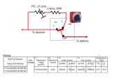
Here is a design for a 24 volt system using a different PTC
View attachment 7677

The same PTC can be used for a 12 volt system
View attachment 7678

I have ordered a few of both PTCs and will see how well it works.
https://www.mouser.com/ProductDetail/81-PTGL06AR0R8M1B5B0 (.8 ohm, 3 amp, 16 volt)
https://www.mouser.com/ProductDetail/81-PTGLCSAS1R2K3B5A0 (1.2 ohm, 5 amp, 51Volt)

OK folks, I got these PTC resistors in
https://www.mouser.com/ProductDetail/81-PTGLCSAS1R2K3B5A0 (1.2 ohm, 5 amp, 51Volt)

I tested the circuit by hooking it up to a bench power supply. (I have not tried it on an inverter yet, but I see no reason it would not work just fine).

For 12 Volts, this what I found with 12 Volts:
1582495334751.png

This is what I measured with 24 volts. Note that I changed the resistor to 15 ohms.
1582495407060.png
 

diy solar

diy solar
Back
Top