diy solar

diy solar

How can I make this 600w Safer?

Either one or the other, no need/sense for both a breaker and a fuse in the same line. If all the breaker is being used for is a switch, use a real switch.
This is what I just got from a YouTuber who built using the same Victron, he uses both a breaker & a fuse this is his explanation:

"Solar panels are rated under STC (standard test conditions). But every once in a while you might encounter more sunlight than STC. This happens to me this time of year with the snow on the ground, cold air temp, and a clear day. So we generally add 25% to be safe. For example, your 600 watts of panels charging 12v = 50 amps. But multiply that by 1.25 = 62.5 amps. So using a 60 amp circuit breaker has the potential to trip once in a while. Very low risk because there is some overhead built into circuit breakers, but the potential is there. I would prefer sizing things a little over. So I might use a 70 amp breaker with 4 gauge wire, and an 80 or 90 amp Class-T fuse. This also helps if you include your continuous duty requirement. Which simply says you need to over-size wires if you use them continuous duty, which this is."
 
It makes no sense. The lower value device will pop before the higher value device, making the higher value device meaningless. His allowance for overpower is fine, but only if his intention is to protect the SCC. You can dead-short the panels and they will be fine.
 
Fusing on the panels can be a little counter intuitive. Here is a good article that @BiduleOhm provided. It is worth a read.
 
This is what I just got from a YouTuber who built using the same Victron, he uses both a breaker & a fuse this is his explanation:

"Solar panels are rated under STC (standard test conditions). But every once in a while you might encounter more sunlight than STC. This happens to me this time of year with the snow on the ground, cold air temp, and a clear day. So we generally add 25% to be safe. For example, your 600 watts of panels charging 12v = 50 amps. But multiply that by 1.25 = 62.5 amps. So using a 60 amp circuit breaker has the potential to trip once in a while. Very low risk because there is some overhead built into circuit breakers, but the potential is there. I would prefer sizing things a little over. So I might use a 70 amp breaker with 4 gauge wire, and an 80 or 90 amp Class-T fuse. This also helps if you include your continuous duty requirement. Which simply says you need to over-size wires if you use them continuous duty, which this is."

He is correct that in winter conditions, power can be greater than 'norm'. What he does not get into is the voltage increase that can happen with cold conditions. Fuses will not do a thing to prevent problems of over-volting a charge controller. Panels are typically specified for 25deg C. As the temp goes down the Voc will go up. Typical temp coefficient for panels is in the .3%/C to .4%/C . If you are dealing with 0F temps, you could be looking at a 15% increase for Voc. If the SCC selected is rated right at the Voc spec.... a 15% increase in Voc puts you well into the danger zone.

There might also be a problem with too much current, but I am not as sure on how to calculate that. Also, since Imp and Isc is so close together, fusing for the cold weather increase might be difficult to do.

One installer back in Missouri told me they just put a 25% margine between the panel voltage and SCC voltage in order to cover cold conditions.
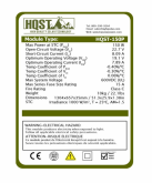
It does not state max voc just voc, how do I work it out? Voc for this 150w panel is 22.7, so 22.7 x 4 (600w) = 90.8 my Victron can handle 150v I'm good correct?
 

Attachments

  • Screen Shot 2020-02-17 at 10.28.13 AM.png
    Screen Shot 2020-02-17 at 10.28.13 AM.png
    401.1 KB · Views: 11
for the resistor, you can just put it in serie with a thermal breaker, when the resistor goes hot, it opens the circuit.
just glue the fuse on the resistor.
 
for the resistor, you can just put it in serie with a thermal breaker, when the resistor goes hot, it opens the circuit.
just glue the fuse on the resistor.

Very good idea, I like that. However be careful about the thermal fuse ratings, this one doesn't have any for DC so I wouldn't use it for this application.
 
Very good idea, I like that. However be careful about the thermal fuse ratings, this one doesn't have any for DC so I wouldn't use it for this application.

Trying to get back to the OP question here:

Yes, with 90v your 150v Victron should be fine.

The resistor was just to be used to precharge right? In that case it will only be used for less than 10 seconds and will dissipate very little current so no need to fuss about fusing or heat generation IMHO.
 
The resistor was just to be used to precharge right? In that case it will only be used for less than 10 seconds and will dissipate very little current so no need to fuss about fusing or heat generation IMHO.

We were discussing the case were you left the switch in the precharge position. Otherwise, yes, no problem with heat dissipation for a few seconds only.
 
well you never know.
if there is a huge load pulling many amps, the resistor will heat very fast.
anyway a design that suppose you have to do something to stay in the safe zone is a bad design.
the thermal fuse is the warranty it will disconnect as soon as the temp goes too hot whatever reason comes first.
thermal fuses come from about 70 degC to 250 deg C, so you have the choice.
you can also use a one button push with a timer that switch between direct connection or resistor.
but this will require a very expensive relay
 
We were discussing the case were you left the switch in the precharge position. Otherwise, yes, no problem with heat dissipation for a few seconds only.

With the switch in the precharge position you are not using the inverter, just charging the capacitor and there will be negligible current. If the resistor is left in parallel while the inverter is running- still negligible current
 
"you are not using the inverter " ... what prevents the situation where inverter is on while switch is on precharge ?
don't let a chance to the chance..
if it is not a failsafe situation, then it is not safe.
 
Last edited:
It does not state max voc just voc, how do I work it out? Voc for this 150w panel is 22.7, so 22.7 x 4 (600w) = 90.8 my Victron can handle 150v I'm good correct?
Yes, you have over 50% margin. That will certainly cover you.

However, here is how you calculate it.
  • The sticker does not say, but almost all solar panels specs are for 25deg C.
  • The sticker says your Voc Temp Coeffficient is -.3%/C.
  • Next you have to decide what your lowest temp will be. A lot of books say to use the historic low for where you are. I have no idea where you are but for this calculation lets pick -10F (-23C).
  • The calculations work like this:
  1. (25c- (-23c)) = 48C (Temp difference between rating temp and worst case)
  2. 48C * .3%/C = 14.4% (percent change in voltage at -23C)
  3. 0.144*90.8V = 13.08 V (Change in voltage at -23C)
  4. 13.08V+90.8V = 103.88 (Voc at -23C)
So, with the 150 volt Victron SCC, you have plenty of margin.

You can easily see how someone could pick a Victron 100 volt SCC thinking they were safe and then get into trouble.
 
With the switch in the precharge position you are not using the inverter, just charging the capacitor and there will be negligible current. If the resistor is left in parallel while the inverter is running- still negligible current

It's very probable you have other loads besides the inverter so the current is not predictable. The best you can do is consider a permanent short and size the resistor accordingly but that's either a very high power resistor or a high value so low current. You can also put a 25 or 50 W resistor + a PTC or thermal fuse to protect it.

I have the same design problem on my DIY disconnect, I chose the smaller resistor + PTC solution (but I'll try to find a better option).
 
the ideal solution would be to have a fuseable device that when cold has a high resistivity and with the current passing through would melt the component to let him go to zero ohm. the device would just keep warm enough to stay fused.
NTC thermistors ?
 
Last edited:
"you are not using the inverter " ... what prevents the situation where inverter is on while switch is on precharge ?
don't let a chance to the chance..
if it is not a failsafe situation, then it is not safe.

Use a momentary switch for the 7 seconds of precharge with the resistor in parallel. Failsafe done
 
It's very probable you have other loads besides the inverter so the current is not predictable. The best you can do is consider a permanent short and size the resistor accordingly but that's either a very high power resistor or a high value so low current. You can also put a 25 or 50 W resistor + a PTC or thermal fuse to protect it.

I have the same design problem on my DIY disconnect, I chose the smaller resistor + PTC solution (but I'll try to find a better option).
Sorry, I am TLA challenged. what is PTC?
 
positive thermal coefficient (resistance increase with temp) versus NTC(negative thermal)
 
Use a momentary switch for the 7 seconds of precharge with the resistor in parallel. Failsafe done
We discussed that in another thread about precharging. That has human fail modes as well.

What if the user forgets to press the momentary switch? Then you are back to over-current on the BMS due to charging the capacitors.

I have not found a solution I am totally happy with but @BiduleOhm comes close with the PTC. The only problem I see is that the inverter could be left in the on position but with a fraction of the current it needs to operate... This is outside of it's design parameters so who knows what will happen.
It will most likely see the voltage get to it's minimum, turn itself on, see the voltage drop and turn itself off and start the cycle over again. That can't be good for it.

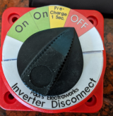
I have played around with an automatic circuit that takes care of everything, but have not come up with an affordable one I like. Till then the rotatory switch is what I use. (My gut tells me the user is less likely to leave the switch in the 'charge' position than to forget to press a momentary button) Note: This is why I make a label for the rotary switch. (See above). It makes it more obvious that the pre-charg position is not an ON position.
 
Unfortunately this is still to low if you want to be able to handle the switch left on the precharge position as 24 / 12 = 2 A and 2 * 24 = 48 W.

Even if you put a 12 Ohm 50 W or 24 Ohm 25 W resistor you'll have to mount it on a heatsink as in free air this type of resistor can only dissipate about 1/3 of their rated power (and that's at incredibly high temperatures too, usually 200 °C).
Yup..... I did the math in my head..... and a pure vacuum does not calculate very well. ? Thanks for catching that.
 
Here are pictures of the labels I put on the rotary switch to help guide the user

1581962390823.png1581962476806.png

Paul's Electroworks is a fictitious company my sister jokingly calls me. (This one is going on her boat)
 
the problem is the switch you show here is pretty expensive .
an electronic kit on ebay is about 5-12$ so it should be possible to make something for reasonable price.
something like a magnetic switch (to avoid big coil).
So basically you need to measure something (resistance, voltage, amp?) let the system charge (you can even measure how much is charged, or simply a timer) then switch the full drive.
with a resistor, the easiest is to measure the voltage across resistor, the voltage should drop when capacitor are charging.
when you put the contact in parallel the voltage will drop to zero
 
with a resistor, the easiest is to measure the voltage across resistor, the voltage should drop when capacitor are charging.
when you put the contact in parallel the voltage will drop to zero

Yep, that's what I do on my BMS, I don't close the disconnect until the voltage accross the resistor is under a safe limit (which remains to be determined...), best solution I can come up with.
 
the problem is the switch you show here is pretty expensive .
an electronic kit on ebay is about 5-12$ so it should be possible to make something for reasonable price.
something like a magnetic switch (to avoid big coil).
So basically you need to measure something (resistance, voltage, amp?) let the system charge (you can even measure how much is charged, or simply a timer) then switch the full drive.
with a resistor, the easiest is to measure the voltage across resistor, the voltage should drop when capacitor are charging.
when you put the contact in parallel the voltage will drop to zero

Yup.... lots of ways to do it. With all of the ideas I have for automating it... you end up needing a big DC contactor for handling the current.
Then you have the cost of the big DC Contactor and the problem of wasted energy in the contactor coil.... not to mention the increasing complexity leading to reduced reliability.

Like I said I have not found a solution I like. Energy Efficiency, Cost and reliability/complexity being the key problems I keep running into. If someone has a good solution.... please share.
 
How far is you run from panels to scc? The efficiency is lost on a mppt from 90v to 14.4 the only advantage of high voltage is for Less voltage drop for long wire runs.
 

diy solar

diy solar
Back
Top