diy solar

diy solar

How close can bare copper bus bars be (12v)

I'm hoping this post starts a discussion, I'm not judging. Let me know if you want a new thread started instead.

Nope, lets discuss!

I have no issue with judgement and no shame. Im always open to any criticism so please feel free to not filter an opinion.

“If you are not willing to be a fool, you can't become a master.”

Jordan b. Peterson

I'm getting ready to put in some copper flat bar, similar to how you're doing. I thought about buying 1" wide flat bar. However, I got to thinking that if the surface contact area is no bigger than 3/4" flat bar would cover, is there any sense in going to 1". Sure 1" flat bar has a bigger cross section and can handle more amps. But if the surface contact area is so much smaller, have I wasted 1/4" of flat bar?

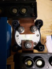
I bought the copper bar based on the surface of the shunt (1.5" wide) and because it would fit everywhere else. The only exception is the bar coming out the top of the switch on the right. It is 2" wide because the out for the switch is like in the picture below but the output (two of them) is where input 1 and input 2 are and the input is where the output is. The 2" bar made it so I could connect to both posts and I cut out the side of the switch housing to let the bar exit the side. It just make it nicer to do.

As Hedges said above, the bigger bar also helps with cooling so it would pull some heat away from the shunt

Not having as much knowledge in this arena as I would like I have simply been trying to err on the side of overkill. You waste a little money but you dont lose it all.
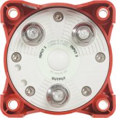

1__60018.1475769558.jpg
 
Not having as much knowledge in this arena as I would like I have simply been trying to err on the side of overkill. You waste a little money but you dont lose it all.

There's a lot to be said for overkill and I'll all for that. The closer you run to the limit of specifications the more likely you are to encounter those pesky edge cases. I'm having trouble getting an order of 3/4" copper flat bar, so I'm considering my options.

I have a similar switch, but with only one input. The studs on the bottom are kind of a pain. The studs are positioned for connections at the 9-3 o'clock positions. But if I wanted the switch at a 90° corner the studs are in the wrong positions if I'm using flat bar.

If you get a wider chunk of copper you can cut it into a hockey stick shape to hit the one post and come off at a 90. Alternatively, if you have access to a tig welder and a bottle of helium you could cut and weld a hockey stick shape. Welding copper isnt hard, but you must have helium. Argon wont work well at all.
 
I was planning to put some heat shrink on the exposed parts of the flat bar. But I now wonder if the heat think would decrease the heat dissipation.

Heat shrink should provide insulation so tables for single conductor in free air might be applicable; consider temperature rating of your heat shrink. Flat bar has greater surface area for a given cross section, so maybe consider ampacity for a smaller wire having similar circumference to area ratio, then scale up for larger total size of flat bar.
If you get a wider chunk of copper you can cut it into a hockey stick shape to hit the one post and come off at a 90. Alternatively, if you have access to a tig welder and a bottle of helium you could cut and weld a hockey stick shape. Welding copper isnt hard, but you must have helium. Argon wont work well at all.

If sufficiently malleable, could bend at 45 degree angle to get 90 degree protrusion.

1640812717702.png
 
If you get a wider chunk of copper you can cut it into a hockey stick shape to hit the one post and come off at a 90. Alternatively, if you have access to a tig welder and a bottle of helium you could cut and weld a hockey stick shape. Welding copper isnt hard, but you must have helium. Argon wont work well at all.

I have a TIG welder and a tank of Helium. But I don't have any rods for Copper.

I've never welded metal that I was expecting to get current through. I wonder how the weld would affect resistance.
 
I have a TIG welder and a tank of Helium. But I don't have any rods for Copper.

I've never welded metal that I was expecting to get current through. I wonder how the weld would affect resistance.
You can use 14/2, 12/2 or any other conductor you want to.

Your tig will need some juice but its a small work piece so that will help. I watched a video 5-10 years ago before I welded copper for the first time. Ill try to find it and post it.
 
That was easier than I expected. I guess not many people welding copper out there. :)


Here is another guy:

 
Not intentionally.
For sure, there just isnt that much demand for it. When I was welding I held a PWP for welding aluminum bus and built 5 or 6 sub stations. all the conductors are aluminum. Just far less expensive.
 
I'll believe Mr TIG any day over that other guy.
Ya, the other guy seems a bit "short bus"

Here is a picture of how I connected to the back side of the one switch with the 2" material. The wider bus bar also moved the fuses over and made room for the battery protects beside the switch.

20211229_170046.jpg
 
In another thread (I think it was another one) I made the observation that slapping two bus bars together didn't double the amp rating. From what I can tell, "stacking" bus bars increases ampacity, but not linearly, and requires an air gap between the bus bars. Since you welded aluminum bus bars, how often did you weld them without an air gap?
 
In another thread (I think it was another one) I made the observation that slapping two bus bars together didn't double the amp rating. From what I can tell, "stacking" bus bars increases ampacity, but not linearly, and requires an air gap between the bus bars. Since you welded aluminum bus bars, how often did you weld them without an air gap?
Never did. All the bus used in substations is 4" sch40 pipe. The butt connections are all done with backing so the only spot that has any double layers is for a few inches at each butt weld. If they needed higher ampacity a second pipe was put in parallel.
 
Back
Top