diy solar

diy solar

How close can bare copper bus bars be (12v)

If the Victrons disconnect while the winch is operating it is likely they will be destroyed, and an arc could form between that gap. Being DC, the arc will not be easily extinguished. Your loads nearly guarantee that the victrons will find plenty of opportunity to open due to low voltage conditions.

Is what you are saying here this:

Because of the draw, the voltage the BMS sees will drop enough that the bms will open the BPs.

Even with an 1100ah battery?

Lastly, offroading with this type of setup is simply not a good idea. The forces that will be placed on those bars as a consequence of vibration, twisting, compression, and other forces will ultimately physically damage the victron. You really need a flexible connection between components of this system, even if they're all mounted to the same 1/4" steel plate. If you manage it get them all on the same plate and within 3" of each other, with the plate only mounted to the vehicle at one point then you only have to face vibration, but even that's enough to cause problems over time.
Nothing but vibration is really a concern for me with this and I have some vibration dampening in the plans. There would certainly be some but I am willing to accept that risk
 
Based on what everyone is saying it is clear the risk of the BPs in this application is probably not worth the rewards. Given what everyone knows so far, is just a straight up contactor the better route? The BMS can still open that through a relay but it sounds as though that may be problematic regardless as the BMS may see enough voltage depression during winching to trigger a low voltage disconnect.
 
Would you mind giving post #17 a read and let me know if this is all necessary?

Guess I should'a done that first.
iu


Winch control switch opening has to deal with any inductive kick negative, or charging as load pulls cable out faster than winch runs.
You said that goes direct to battery, not through BMS. So BMS and other electronics aren't exposed to it. Just the switch shipped with/in winch.

As people noted, winch could cause battery voltage to drop below low-voltage disconnect. No winch current though BMS, but it would interrupt control circuit, would also interrupt any inverter current which happened to be drawn at the moment.

Does BMS disconnect instantly for low battery voltage, or does it allow some seconds for starting surge?

The motors are not permanent magnet motors. Not an issue then?

Nope. Once switch opens, I don't think they generate any voltage.
 
Am I missing something here? I mean... these are both + right? so even if they touch it would not short, it would just make this device not do its job? I mean I might be missing something...
 
Winch control switch opening has to deal with any inductive kick negative, or charging as load pulls cable out faster than winch runs.
You said that goes direct to battery, not through BMS. So BMS and other electronics aren't exposed to it. Just the switch shipped with/in winch.

It goes directly to the battery through the battery protects (original plan) which the BMS would open if low voltage disconnect is reached.


As people noted, winch could cause battery voltage to drop below low-voltage disconnect. No winch current though BMS, but it would interrupt control circuit, would also interrupt any inverter current which happened to be drawn at the moment.

Does BMS disconnect instantly for low battery voltage, or does it allow some seconds for starting surge?
I am using an electrodacus and not sure if it has a delay or not. I will find out later tonight.
 
Am I missing something here? I mean... these are both + right? so even if they touch it would not short, it would just make this device not do its job? I mean I might be missing something...

You are not missing anything. A short across the bars was never a concern for me. My question was more along the lines of if the battery protect opened during high current, is there any possibility that the current "inertia" would cause an arc to jump between the two bus bars.

The thread is off topic now which for me is great because it is driving more thought and pushing me to dive deeper into potential issues regarding using the BPs in this way.
 
Couldnt we simply shorten the bars a little to make them less likely to causes issues? Then 3d print something that slides over both buss bars and insulates them from each other and from ground??

In fact just the 3d printed encasement, physically binding the bars together would significantly decrease the toque on those lugs... just a thought, kinda a 2 birds with one stone kinda deal
Thanks for the input but I am really not concerned about the connections themselves. After all the very good points regarding the issues the type of load can cause there is a really good chance I will not even proceed with the BPs. Still thinking.
 
So this winch can draw max amp of say 450+ amps, but that’s at max capacity. If your typically pulling say 1/4 the winch rating, the current will substantially be under that value. I forget if the current draw is linear to load or exponential.


Also if you’re designing for 600 amps, what sort of BMS combo supports this rating? 3 200A units?

I’d just invest in a quality disconnect/shut off rated for 800amps, save the Victron stuff for something else.
 
So this winch can draw max amp of say 450+ amps, but that’s at max capacity. If your typically pulling say 1/4 the winch rating, the current will substantially be under that value. I forget if the current draw is linear to load or exponential.

The loads are extremely variable and it the load and line tension vary based on how much line is on the drum. If you are down to the last wrap on the drum you have far greater work advantage vs if all the line is on the drum line speed is much higher but motor has to work a lot harder for a given pull.

Also if you’re designing for 600 amps, what sort of BMS combo supports this rating? 3 200A units?

Im using an electrodacus so no current through the bms. It turns components on and off based on battery status.

I’d just invest in a quality disconnect/shut off rated for 800amps, save the Victron stuff for something else.

Leaning heavily this way. Can you make any suggestions for hardware?

Got a picture of your Volvo?
 
"
  • o Maximum Coil Energy Draw: 18W
  • o 1.5A Power Draw
"

OK for intermittent use of winch.
Not what you want as a contactor controlled by BMS.
Ya, the coil is a pig. I was trying to avoid going this route which is why I went with the BPs but now with the obvious issues with those Im reconsidering contactors. I have considered SSRs, I had been pointed towards some 1000amp SSRs in the past before I decided to go with the BPs. Any suggestions or recommendations on hardware?
 
I'm not familiar enough to recommend one for that application.
If electromechanical, you want an "economizer", which allows high coil current for pull-in, then low to hold.

The name Gigavac comes up a lot. I think one of the guys here used it between his lithium battery and inverter but it kept welding contacts.


A relay I use is branded SMA (made by one of the other big names of course). It switches 3 poles of 120 or 240 VAC.
What it has was dual winding coil and an extra contact, normally closed (which shorts out high resistance coil). It slams shut with battery applied to low resistance coil (48V into 10 ohms, 5A or 250W), opening the extra contact and inserting the high resistance coil.
 

Simple disconnect switch rated at 600 amps.

Seeing the winch control switch will be making and breaking the winch solenoid voltage, you don’t need anything that needs to interrupt high current.

I haven’t had my 740GLE for at least 13-15 years, did have a sweet 960 wagon up until 2009. Damn I miss that thing.
 

Attachments

  • 51A6A792-58A4-4A15-8F58-089485755BC1.jpeg
    51A6A792-58A4-4A15-8F58-089485755BC1.jpeg
    560.5 KB · Views: 10

Simple disconnect switch rated at 600 amps.

Seeing the winch control switch will be making and breaking the winch solenoid voltage, you don’t need anything that needs to interrupt high current.

I haven’t had my 740GLE for at least 13-15 years, did have a sweet 960 wagon up until 2009. Damn I miss that thing.
I have one of those for the manual disconnect for this circuit. I want something so the BMS can shut it down if the battery is low also so there is the possibility that it will have to interrupt current.

I have never had one but have always loved those old square Volvos.
 
How much winching you planning on doing? Winching up the entire trail?

With a possible .5c draw on the 1100ah 12v battery, I’d wager under max load the battery voltage will drop pretty good causing what ever relay to open.
 
How much winching you planning on doing? Winching up the entire trail?

With a possible .5c draw on the 1100ah 12v battery, I’d wager under max load the battery voltage will drop pretty good causing what ever relay to open.
The truck is unproven so I have no idea how much I will need to be doing. It is a big heavy truck locked front and rear but is a bit on the top heavy side. I need to be prepared for the worst as it is more than possible that I could have to do several consecutive pulls up a steep slippery hill.
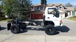
This is the truck (those are 40" tires)

20200904_160143 (1) (1).jpg

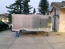
This is going on the back:

20210908_202342 (1).jpg

As for the battery voltage dropping. I started thinking about that yesterday after someone brought it up and at this point I think I am going to just get everything installed without a BMS LVD and do some testing to see what happens in the real world before spending any more money.
 
Back
Top