diy solar

diy solar

How close to failure is this MPPT+PV package and is there a way to protect against high voltage?

For two strings it is not needed. Save your money till you have more strings. That could be expanded but a lot of work.

Needed? Like everything else in life, it depends: for an electrician or someone doing this for a while? Maybe not. But for someone going over this the very first time? Maybe yes.

If you have the patience and the desire to read 4 pages of technical jargon I personally don't fully understand, sprinkled with arrogant subtleties disguised as help from some key Trolls, you'll realize that $100 is an excellent price for me to move on. I actually feel like it is a bargain!
 
He is spending his own money.
I'm trying to discourage him. lol

(y) (y) (y)

You are good, bro. I hear you.

But I suspect all of this comes so easy and natural for you that you loose touch with how hard it is for someone new in the field to learn the science. And the learning curve comes with a component that costs a lot more than money, IMHO: time.

What am I really saving (or wasting) trying to reduce a final combiner box price of $84 ($100-$16 for Y splitters) when I don't master the science behind to build my own? It has taken 401 posts to get to this Combiner Box. How many more posts (and time) would take to build my own box and save $30?
 
Solar arrays having higher current availability (parallel strings of solar panels) than the maximum overcurrent protective device rating specified for the panel shall be protected from overcurrent. EXCEPT when the short circuit currents from all sources do not exceed the ampacity of the wires and maximum overcurrent protective device size rating specified on the PV module nameplate.
 
Solar arrays having higher current availability (parallel strings of solar panels) than the maximum overcurrent protective device rating specified for the panel shall be protected from overcurrent. EXCEPT when the short circuit currents from all sources do not exceed the ampacity of the wires and maximum overcurrent protective device size rating specified on the PV module nameplate.
What does the above mean to you, in plain english, for a 2P config with the following panel specs:
Panel Isc=13.85A
Panel Max Fuse Rating=25A
 
(y) (y) (y)

You are good, bro. I hear you.

But I suspect all of this comes so easy and natural for you that you loose touch with how hard it is for someone new in the field to learn the science. And the learning curve comes with a component that costs a lot more than money, IMHO: time.

What am I really saving (or wasting) trying to reduce a final combiner box price of $84 ($100-$16 for Y splitters) when I don't master the science behind to build my own? It has taken 401 posts to get to this Combiner Box. How many more posts (and time) would take to build my own box and save $30?
What I was saying was that with only two strings, you don't need any box. But I agree that it is your money. And if $100 gives you piece of mind. Then it is probably worth every penny.
 
What does the above mean to you, in plain english, for a 2P config with the following panel specs:
Panel Isc=13.85A
Panel Max Fuse Rating=25A


Two strings in parallel, no fuse per string needed. (each source pushes current in opposite directions, doesn't add.)

13.85 x 1.56 = 21.6A, so for 3 or more strings, each requires a fuse between 22A and 25A.

Home run wire for 2p must have ampacity at least 44A (after any required deratings). OCP not required but if used must be rated that amount or greater (in which case it is good form to use wire with ampacity at least as high as OCP rating.)
 
Two strings in parallel, no fuse per string needed. (each source pushes current in opposite directions, doesn't add.)
(y)

13.85 x 1.56 = 21.6A, so for 3 or more strings, each requires a fuse between 22A and 25A.
(y)

Home run wire for 2p must have ampacity at least 44A (after any required deratings). OCP not required but if used must be rated that amount or greater (in which case it is good form to use wire with ampacity at least as high as OCP rating.)
(y)

Thank you for the translation, much appreciated.
 
.... but I still would need a disconnect, main breaker and hopefully a SPD.

So you see where this leads me, right?
None of that is required.
I do recommend a disconnect near the SCC for maintenance. And a SPD is good insurance.
 
None of that is required.
I do recommend a disconnect near the SCC for maintenance. And a SPD is good insurance.
We are going in circles. I don't know what to do with this information, hence my preference for a plug-and-play box solution.

I appreciate the effort, but it is just not complete enough so that I can run with it.
 
We are going in circles. I don't know what to do with this information, hence my preference for a plug-and-play box solution.

I appreciate the effort, but it is just not complete enough so that I can run with it.
Sorry, I'm not trying to confuse you.
The requirements changed, when you decided to only have 2 strings. As in, there are no requirements for fusing or any kind of OCP. So, all that is left is what you might want for convenience.
Which I why I only gave recommendations for options.
A disconnect near the SCC is just handy for maintenance. And a SPD is just added protection for your SCC. If there's a nearby lighting strike.
But you aren't required to do either one.
You are completely fine with just connecting your panels straight to the SCC.
 
Sorry, I'm not trying to confuse you.
It is confusing (to me) but it is certainly not your fault.

A disconnect near the SCC is just handy for maintenance. And a SPD is just added protection for your SCC. If there's a nearby lighting strike.
But you aren't required to do either one.
You are completely fine with just connecting your panels straight to the SCC.
Totally understand it.

What parts would you electively buy, for this installation, if you wanted to add a disconnect and SPD? Could you produce a parts/product list?
 
@timselectric

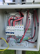
Okay, using the sample installation photo as reference, this is how I see this is wired:

- Combined array string (black/red) to main input breaker (bottom)
- From breaker output to system (MPPT) AND to SPD (it looks like in parallel)
- Ground from SPD to grounding wire (and grounding box)

Did I get this correct?

Two questions regarding the sample install photo:

- how come the input wire into the breaker is WAY smaller than the output wire out of the breaker? What I am missing here?
- what is the yellow wire connected to the box?
 
@timselectric

Okay, using the sample installation photo as reference, this is how I see this is wired:

- Combined array string (black/red) to main input breaker (bottom)

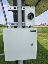
Input from panels comes into top of breakers. SPD's are ahead of breakers in parallel. At the bottom of the breakers, the wire runs up to an IMO disconnect, then back down into conduit at bottom of box to the house. The PV disconnect should be accessible for shutdown of PV if there was a fire at the house. The box is locked, access requires a key or screwdriver. If the disconnecting means is inside a locked box, then it really isn't an accessible switch. Some use the boxes with flip up covers, around here it snows and blows in winter, a flip up cover would last a few weeks before it was ripped off.

There has been debate to install SPD's before or after. I prefer before the breakers.
- From breaker output to system (MPPT) AND to SPD (it looks like in parallel)
You have it backwards, wires coming down mast head are from panels, but yes, in parallel.

- Ground from SPD to grounding wire (and grounding box)

And ground runs all the way to system ground rod at house.

Did I get this correct?

Two questions regarding the sample install photo:

- how come the input wire into the breaker is WAY smaller than the output wire out of the breaker? What I am missing here?

PV wire has thicker insulation. It also is 8AWG PV wire from panels to breakers, #10 from breakers to rest of system. Breakers are 20A, note the C20 on breaker. It cost me the same for 8AWG PV wire as #10 would.

- what is the yellow wire connected to the box?
The door needs a ground wire as it is metal, came with the box.
 
@timselectric

Okay, using the sample installation photo as reference, this is how I see this is wired:

- Combined array string (black/red) to main input breaker (bottom)
- From breaker output to system (MPPT) AND to SPD (it looks like in parallel)
- Ground from SPD to grounding wire (and grounding box)

Did I get this correct?

Two questions regarding the sample install photo:

- how come the input wire into the breaker is WAY smaller than the output wire out of the breaker? What I am missing here?
- what is the yellow wire connected to the box?
Panels are the source of power. So, they connect to the top of breaker. And just like Zwy , I prefer the SPD on the source side of the breaker.
 
Input from panels comes into top of breakers.
Got it, I had it reversed.

The PV disconnect should be accessible for shutdown of PV if there was a fire at the house.
Okay, so you had to add an extra disconnect outside the breaker box ( the IMO).

But if it weren't locked then you would not need the extra outside disconnect. Is this correct?

I am trying to understand whether I need or not an extra disconnect on my system. I suspect not, since my breaker box will not be locked.

There has been debate to install SPD's before or after. I prefer before the breakers.
Got it.

PV wire has thicker insulation. It also is 8AWG PV wire from panels to breakers, #10 from breakers to rest of system. Breakers are 20A, note the C20 on breaker. It cost me the same for 8AWG PV wire as #10 would.
Understood. But why didn't you choose then to run the oversized 8AWG PV downstream? Since it is the same price, wouldn't that help by reducing resistance? Just trying to understand how /why you made these choices.
 
Got it, I had it reversed.


Okay, so you had to add an extra disconnect outside the breaker box ( the IMO).

But if it weren't locked then you would not need the extra outside disconnect. Is this correct?

It's a fine line, the PV disconnect needs to be accessible. But anything with open terminals like the breakers and SPD's need to be in an enclosure that is not easily accessible. For example a young person could open a door and reach in and get shocked.

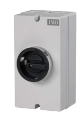
I have an IMO on each end, this ensures if I'm working on the system with each disconnect locked and tagged, I won't get shocked if someone turned on the array end. I like the IMO, it is reasonable in price, IP rated for outdoor use. It uses a knife switch with spring action to break the arc. Do you need the IMO disconnect? Not in some AHJ's. It is a matter of convenience and safety, I want the ability to easily disconnect. More reading on the subject here. https://diysolarforum.com/threads/nec-compliance-on-pv-disconnect-boxes.56025/


I am trying to understand whether I need or not an extra disconnect on my system. I suspect not, since my breaker box will not be locked.

The breaker box will need to be either locked or open terminals/wiring needs to be covered and inaccessible. This is why you see combiner boxes that have a clear plastic shield inside the box if the internals are exposed. Like this one Ian sells: https://watts247.com/product/solar-panel-combiner-box-4-circuits-to-2/ Notice the plexiglass preventing access to terminals.

Whether your AHJ requires the disconnect or not is a question for your AHJ. I didn't have inspection here, but I still installed the disconnect.

Got it.


Understood. But why didn't you choose then to run the oversized 8AWG PV downstream? Since it is the same price, wouldn't that help by reducing resistance? Just trying to understand how /why you made these choices.
I ran THWN-2 enclosed in pvc underground 420 feet to the house. It doesn't need UV protection there. PV wire exposed needs UV protection, that is why the wire runs into the box, then switches to THWN-2. Way cheaper running THWN-2 buying it in 500 foot spools. PV wire 500 feet- $490 per roll, I would have needed 4 rolls plus a ground wire. https://signaturesolar.com/500-ft-12-awg-copper-pv-wire-black-and-red-30-amp/

I purchased five 500 foot rolls of 10AWG THWN-2 for $600

10AWG PV wire versus 8AWG PV wire was about the same price for the 30 feet I purchased off Amazon. It ended up almost free, it came and the ends were not installed correctly. Amazon refunded my money and let me keep the wire. I just purchased a MC4 crimper and terminals and installed new ends.
 
Do you need the IMO disconnect? Not in some AHJ's. It is a matter of convenience and safety, I want the ability to easily disconnect.
Very clear, thanks again.

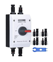
I want a disconnect along the house wall - my choice, not necessarily code requirement. Just for quick disconnect access - the MPPT and batteries and the PV breakers are located in exterior shed. I would like faster access to PV disconnect, hence the desire to install a similar DC disconnect outside the house.

What do you think would be easier to mount on the exterior house wall: a terminal-type DC disconnect (similar to IMO) or a MC4 -type DC disconnect (similar to DIHOOL)?

1689805831233.png
1689805847365.png

I will have the 3/4" PVC conduit running along the way with a pair of 8AWG and the ground cable in it. I just don't see how to physically add the disconnect at eye level mounted on the wall and having the conduit coming from the roof.

Any other photo showing how this could/should be accomplished?
 

diy solar

diy solar
Back
Top