diy solar

diy solar

How do I stay safe installing my solar if I didnt buy a battery cutoff, or isolator/breakers and general safety advice for installing/uninstalling?

Gueyog8a7

New Member
Joined
Nov 17, 2023
Messages
304
Location
UK
I will first note that I am only working with a 12v system and have no plans to implement ac so from what I read that does limit the possible dangers.

I got, what I hope is, the remainder of my kit yesterday and realized I dont have the first clue about safety of installing this stuff. Even the Will Prowse videos that claim to be for beginners he seems to assume a previous background in electrical wiring and doesnt really explain about anything when installing stuff.

Likewise with all other so called basic videos I have seen so far. I have seen no mention of safety precautions that are required when touching wires in the system. Is that because they are not dangerous. I certainly thought it better to check that here first.

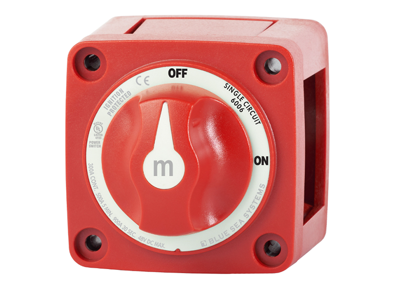
The general consensus when I was asking about breakers and isolators were that they are just a convenience rather than a safety measure and that fusing the wires is all that is required for safety. I just realized yesterday though, once your connection is live to the battery how do you then disconnect and mess about with wires without risk of electrocution.

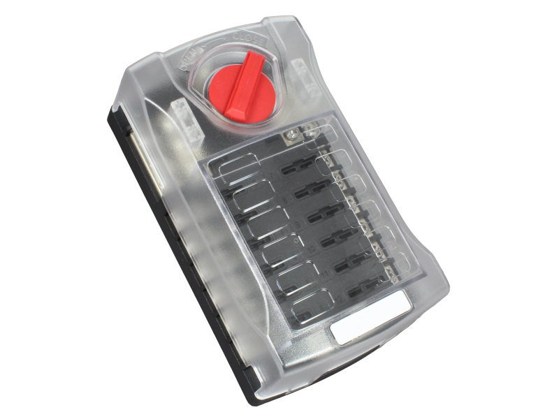
So I thought I would keep it simple and only use megafuses for the links between battery to blade fuse box and battery to mppt. As such though how do I disconnect safely to work on the system because the act of disconnecting, without a breaker/disconnect must then entail touching a live wire to disconnect the fuse. Is this safe to do or not?

Oh btw the way on wills minimalist youtube video I am confused as to why he connects the mppt to the blade fuse block rather than the battery, the latter which seems to be most common practice in other setups. Again, he doesnt bother explaining this at all. Anyway, since this seems to be the exceptional case I am just going to connect them to the battery but I am interested to know why he did it like that.

I ask for both the link to the battery to blade fuse block and battery to mppt. Also what about the panels to the mppt? How to disconnect those since, as I made in another post, I have not used fuses or a dc isolator. In antoher reply elsewhere they mentioned to simple disconnect the positive from the panels to the mppt, but again, is this safe to touch since it will be live.
 
First things first ...
What are the details of the battery?
Where are you using this?
 
First things first ...
What are the details of the battery?
Where are you using this?
Lifepo4 105ah battery. Fogstar Drift if you want the specific make.

Will be in small van (ford transit connect). 200w panels, epever tracer 4215bn.
 
OK, lithium batteries can deliver much higher current than lead-acid, probably between 5000A and 20,000A.
Make sure you never short them, keep wire ends apart, don't let metal tools cause a short. Insulated handles on wrenches, of course don't wear metal jewelry.
Good to wear safety goggles, for protection from splattered molten metal.

Uses Eve cells, maybe these


< 0.5 milliohm per cell
3.4V / 0.0005 ohms = 6800A

Should use a fuse that is rated 6800 AIC or higher at 12V. Locate close enough to battery that no shorts could occur before it.
Blue Sea sells good brands.


Battery spec max 100A discharge.
100A x 1.25 nuisance margin x 1.12 ripple factor = 140A or larger fuse to carry max current. (BMS in battery should protect if loads draw too much. Fuse protects against short circuit.) So 150A fuse.

This fuse has only 5000A interrupt capability, not quite enough: https://www.bluesea.com/products/5258/AMI___MIDI_Fuse_-_150_Amp

MRBF, 10,000A is sufficient. Not sure if it mechanically fits the battery terminals: https://www.bluesea.com/products/5185/MRBF_Terminal_Fuse_-_150A

This one, 2000A is not nearly enough: https://www.bluesea.com/products/5103/MEGA___AMG_Fuse_-_150_Amp

Class T, 20,000A is quite good. What most of us use for 48V batteries: https://www.bluesea.com/products/5114/Fuse_A3T___Class_T_150_Amp

ANL says 6000A at 32V, maybe higher current at 12V is documented elsewhere? https://www.bluesea.com/products/5127/ANL_Fuse_-_150_Amp

I'm not finding lower voltage ratings for ANL, but this gives 80V and 32V: https://www.grainger.com/product/BUSSMANN-Forklift-Limiter-Fuse-150-1DC54


With higher voltage batteries and larger inverters, people have to precharge capacitors in inverter, otherwise just connecting battery causes BMS to disconnect or fuse to blow. You probably don't have to worry about that with 12V.
12VDC isn't a shock hazard, just a high current shorting hazard.

PV panels can give you a shock, especially if you are wet. When connected to an inverter, sometimes PV panel frames carry AC, so grounding them with a wire back to the inverter helps. Not sure if any SCC do that. It is good for your panels to ground to vehicle body, also SCC chassis grounded.

If you do use an inverter, the AC of course is a shock hazard. GFCI outlet would help with safety. Ground chassis of inverter to chassis of vehicle - otherwise it may carry AC. Even for a while after battery is disconnected!

 
You comment on different methods of connecting stuff together. There is a diference between demonstration setups compared to best engineering practice for safe reliable mobile systems.
Regarding breakers and fuses, it's more common in Europe to use fuses for overcurrent protection. The readily available breakers from Amazon and eBay are useless and a safety issue. Don't use blade fuses for current above 20 amps

As discussed a main battery fuse is a really good idea. This fuse holder,
And fuse, suitable for your actual load on the battery and cables used, example 100 amps, ( battery is limited to 100 amps)

Fit any other fuses after this main fuse, midi fuse and holder 30 to 100 amp.

For much of the cables, fuse holders, and associated parts 12v planet is a useful supplier,

The panels in series at below 50 volts are not considered a risk , having an isolation switch in series is useful, connect up with the switch in the off position.

When wiring up or making modification, isolate the panels and disconnect the battery negative. When finished the work connect battery first then panels.

The most danger is from high current from the battery, hence the recomendation of mounting the MRBF fuse directly on the battery positive post.

Typical ciruit below, correction to circuit main fuse before optional battery isolator. Note the use of buss bars. Not shown is a negative cable from negative buss bar to vehicle metal. Also note the position of a shunt in the negative path. This is optional but fitting a battery monitor monitor is advised for battery house keeping.

Your Fogstar battery may be involved in a batch shipped with a faulty BMS that needs updating. Contact Fogstar for advice.
Screenshot_20230905-200359_Chrome~2.jpg
 
Last edited:
OK, lithium batteries can deliver much higher current than lead-acid, probably between 5000A and 20,000A.
Make sure you never short them, keep wire ends apart, don't let metal tools cause a short. Insulated handles on wrenches, of course don't wear metal jewelry.
Good to wear safety goggles, for protection from splattered molten metal.

Uses Eve cells, maybe these


< 0.5 milliohm per cell
3.4V / 0.0005 ohms = 6800A

Should use a fuse that is rated 6800 AIC or higher at 12V. Locate close enough to battery that no shorts could occur before it.
Blue Sea sells good brands.


Battery spec max 100A discharge.
100A x 1.25 nuisance margin x 1.12 ripple factor = 140A or larger fuse to carry max current. (BMS in battery should protect if loads draw too much. Fuse protects against short circuit.) So 150A fuse.

This fuse has only 5000A interrupt capability, not quite enough: https://www.bluesea.com/products/5258/AMI___MIDI_Fuse_-_150_Amp

MRBF, 10,000A is sufficient. Not sure if it mechanically fits the battery terminals: https://www.bluesea.com/products/5185/MRBF_Terminal_Fuse_-_150A

This one, 2000A is not nearly enough: https://www.bluesea.com/products/5103/MEGA___AMG_Fuse_-_150_Amp

Class T, 20,000A is quite good. What most of us use for 48V batteries: https://www.bluesea.com/products/5114/Fuse_A3T___Class_T_150_Amp

ANL says 6000A at 32V, maybe higher current at 12V is documented elsewhere? https://www.bluesea.com/products/5127/ANL_Fuse_-_150_Amp

I'm not finding lower voltage ratings for ANL, but this gives 80V and 32V: https://www.grainger.com/product/BUSSMANN-Forklift-Limiter-Fuse-150-1DC54


With higher voltage batteries and larger inverters, people have to precharge capacitors in inverter, otherwise just connecting battery causes BMS to disconnect or fuse to blow. You probably don't have to worry about that with 12V.
12VDC isn't a shock hazard, just a high current shorting hazard.

PV panels can give you a shock, especially if you are wet. When connected to an inverter, sometimes PV panel frames carry AC, so grounding them with a wire back to the inverter helps. Not sure if any SCC do that. It is good for your panels to ground to vehicle body, also SCC chassis grounded.

If you do use an inverter, the AC of course is a shock hazard. GFCI outlet would help with safety. Ground chassis of inverter to chassis of vehicle - otherwise it may carry AC. Even for a while after battery is disconnected!

You comment on different methods of connecting stuff together. There is a diference between demonstration setups compared to best engineering practice for safe reliable mobile systems.
Regarding breakers and fuses, it's more common in Europe to use fuses for overcurrent protection. The readily available breakers from Amazon and eBay are useless and a safety issue. Don't use blade fuses for current above 20 amps

As discussed a main battery fuse is a really good idea. This fuse holder,
And fuse, suitable for your actual load on the battery and cables used, example 100 amps, ( battery is limited to 100 amps)

Fit any other fuses after this main fuse, midi fuse and holder 30 to 100 amp.

For much of the cables, fuse holders, and associated parts 12v planet is a useful supplier,

The panels in series at below 50 volts are not considered a risk , having an isolation switch in series is useful, connect up with the switch in the off position.

When wiring up or making modification, isolate the panels and disconnect the battery negative. When finished the work connect battery first then panels.

The most danger is from high current from the battery, hence the recomendation of mounting the MRBF fuse directly on the battery positive post.

Typical ciruit below, correction to circuit main fuse before optional battery isolator. Note the use of buss bars. Not shown is a negative cable from negative buss bar to vehicle metal. Also note the position of a shunt in the negative path. This is optional but fitting a battery monitor monitor is advised for battery house keeping.

Your Fogstar battery may be involved in a batch shipped with a faulty BMS that needs updating. Contact Fogstar for advice.
View attachment 179430


Thanks both.

What does shorting mean? I know the term short circuit but not what it pertains to.

As I said I already bought all the kit. I had bought 170a rated wire for batt to mppt and batt to blade fuse holder.

I bought 150a fuses with megalink fuse holders.

As most others who responded online yesterday said 12v is not a problem when handling the wires since it is not enough to penetrate the skin I carried on with putting stuff together. Just to get out of the way, due to previous comments, I started by placing fingers on both + and - of the battery and didnt feel anything so felt better working on the system once I had done it. Was that shorting it? :oops:

I worked through the day and connected the 150a fuses in the spots next to + of the battery, cutting the wires and terminating with O rings for the connections except to mppt which I screwed to the terminals.

I was able to get power to the mppt and also made first connection on blade fuse holder by connecting the led light.

No shocks or surprises thankfully. Does all sound ok of my setup?

Where do you get that info about faulty BMS for fogstar? I quickly did a search and didnt see any results for that.

So to reiterate both mppt and fuse blade + wires are fused with 150a fuses.

I will note that most of the wiring related gear has been bought from 12volt planet, which you recommend above so seems the kit should be reliable.
 
bought 150a fuses
This fuse is unsuitable for the main fuse on a 12v lithium battery. If an accidental 'shorting ' occurs where a unwanted connection occurs between battery positive and negative anywhere in the system, dropped tool, frayed cable, fault within equipment, vehicle accident damage, a high current, 7000 amps could flow. Hopefully the battery BMS will cut of the current, but this is not guaranteed.
Not all fuses can tollerate high current, the link will fail but the high current 'jumps the gap' and flows into the rest of the system. Megs fuse is only rated up to 2000 amps. Thus its recommended to use MRBF or classT or HRC master fuse at the battery.

The cable and solar controller overcurrent protection, the controler is rated at 40 amps so the fuse should be slightly higher, say 50amp midi link fuse.

Typical total current from the distribution fuse box will be much less than 150 amps, usually the fuse box is protected by a 30 or 40 amp fuse. ( The fuse box may be rated maximum 100 A, many are much less)

Regarding Fogstar, one system in a van conversion for a client, was showing BMS fault conditions and incorrect SOC. Fogstar confirmed that some batteries had incorrect programming and offered a softwere update. Only a small batch had the issue.
Note your 105 Ah battery is limited to 100 amps.

Re 170 amp cable, 25mm2 . Apart from the battery to fuse holder and battery negative to negative buss bar, cable feeds to solar controler and fuse distribution could be lower gauge with the fuses I suggest.

Mike
 
Just buy yourself some basic cutoff switches. They don't cost much at all.

Think about these scenarios:

- You're working on the system and you drop a spanner or screwdriver near your battery.
- You turn everything off but leave the battery connected and then a random wire from your system contacts it.
- You want to change the battery but to do so you have to break the circuit somewhere, which can generate sparks.
- Your wires start to glow hot because you forgot to upgrade one wire as you expanded the system, the fuse hasn't popped though because the current isn't actually high enough to cut it off, now what do you do?

I have a small homebrew system that I've cobbled together. One of the first things I bought was switches capable of switching, trips and breakers for the highest current I envisage being delivered (even in only in their "peak" rating).

Every time I meddle on the system, I cut the battery off. It's just too easy to forget it's live or slip or make a mistake. Tell me - with your charge controller, is your + terminal next to your - terminal? How about all the devices you have connected to it? What's the smallest gap you have between a + and a - that goes to the battery? It's probably millimetres. Now consider what happens when your screwdriver slips, or the wire you're feeding in is slightly splayed and touches the other side?

A battery as you describe is a portable welding station, too, it can deliver such high current. If you join those terminals with a metal object, it will fuse (as in the meaning "join together") metal. Now your dropped-spanner is welded between +ve and -ve terminals...

This is why I have my batteries in a box, the box is protected from anything dropping on it, the wires out of the box go immediately into a switch, plus fuses, plus circuit breakers, before getting to my main draw (an inverter capable of 6000W - that inverter once back-fed from its positive INPUT TERMINAL to Earth after it was switched off, disconnected and all wires removed for about 10 minutes. The INPUT terminal. I was unscrewing the dead-by-switch positive input cable, that was connected to nothing else, and my screwdriver contacted the positive INPUT terminal (with 0v going into it) and the chassis (properly grounded) and sparked/arced like hell. Because the capacitor in the inverter was holding enough charge to backfeed out through the input terminal). That main draw then also has multiple safety devices throughout.

My batteries and solar panels both have a cut-off switch before the solar controller (how else are you going to kill power to your controller if it goes wrong and needs resetting?).

Hell, even my "voltage sense" cable that I use to determine if a remote ATS should switch on or off has a 1A fuse on it near the battery that I put there, and a manual cutoff to allow me to override it. Because without that, you have a thousand amps heading down a tiny, thin voltage-sense wire if something goes wrong, even if that's only for a few seconds. That's a fire even if the fuse pops. My RS485 devices are optically isolated and the board that does that also has a cutoff switch before it.

I can isolate and work on any part of my system without having to pull a fuse (fuses have power going through them, hence can arc when you remove them... even a fused spur can generate an arc when you remove / replace the fuse in ordinary electricals), by turning a knob somewhere.

For the sake of a cheap switch, just put some safety into your system. Because when things start smelling/getting warm, you aren't going to want to have to work out which fuse is doing what, where and how to remove it safely while things are heating/arcing/sparking around you - and what are you removing those fuses with? Bare hands? A metal screwdriver?

I am about to install a big red emergency stop button on the wall of my little setup, because although *I* know which switch does what, nobody else would... so why not have a big stop button that just cuts everything? I also put switches BETWEEN batteries in my parallel setup, so I can isolate the batteries from each other if required (say you have a dead battery in your parallel chain, that could overheat - but if you can only cut off ALL your batteries from the system, those batteries are STILL CONNECTED TO EACH OTHER, it's still going to overcharge, overheat, etc. and you won't be removing a battery terminal in a hurry).

DC12V @ 1000A is just as dangerous as AC, if not more. DC makes you "clamp" your hand if you find yourself part of the circuit. Now you can't let go of that hot live wire. AC shocks your hand away (generally speaking). Current is just as dangerous as "voltage", is the main source of heat and fire in cables, and can weld metal at the kinds of current you're handling (whether the spec sheet says it or not). Your 12V system is actually more dangerous than a 48V system, for example, because it will be carrying higher current for the same power, and that higher current requires thicker cables and better connections to handle it properly.

I designed my small 12V system deliberately to "start dangerous", if you think of it that way. If my 12V system can handle 400A, and my cables are specced to handle that from the start, then when I go to 24V / 48V the exact same cables will be SAFER. They'll have half / one quarter the current that they were specced to handle.

Hell, I removed a 13A fuse from a mains lead and put a 1A fuse in deliberately when I was first starting out. When it did pop one day, I realised that I'd forgotten all about that - and it's that easy to suddenly forget and exceed your design somewhere in the system without realising / remembering. Fortunately, because my 1A fuse was nothing but me being abundantly cautious, I was able to just increase the fuse size to take account of the system that had evolved by that point. Now consider what cables you put in on day one and test with 100W, but then are still there years later when you're using 1000W, and so on.

This stuff can be dangerous. Welding, shocking, clamping, arcing, heating to the point of catching thick cables on fire, etc. etc. We're all "DIY" and many of us have never done this stuff before and learn as we go, whether that's from zero knowledge, or electrical experts. If you - like me - started at the zero-knowledge end of the scale, and you feel enough to question why there is no cutoff switch?

Put some cutoff switches in it.
 
"Shorting" means connecting a piece of metal that is near zero ohms between battery positive and negative. High current will flow, limited only by resistance of the metal and internal resistance of the battery, around 6000A for your battery. Multiply by 12V, and about 72,000W is dissipated in the piece of metal and in the battery. The battery's internal BMS may or may not survive trying to stop that. A suitable fuse will stop the current, although BMS may not survive.

The most immediate risk of such a short is blasting a splatter of molten metal in your face. It can also start a fire, cause a battery to burst, weld a ring and burn your finger off. It can ignite gasses from a battery, typically hydrogen explosion for lead-acid, LiFePO4 gasses also burn if ignited. Other lithium chemistries will vent above auto-ignition temperature and spontaneously burn.

When you touch it with dry hands, you're around 100,000 ohms so about 0.0001A flows and you don't feel a thing.
If your hands were wet, or you punctured the skin, then even at 12V it might be enough current to cause a problem.
We test 9V batteries by touching them to our tongue.
If you touch 200V, the dielectric provided by your skin breaks down and the resistance though moist tissue is 1000 ohms. 0.2A flows. DC will cause burns after some time. AC, 60 Hz, scrambles ion polarity in the heart, changing or stopping the heart rhythm (ask me how I know).


Cutoff switches - only good if quality (name brand), cheap ones will overheat and burn at 100A.
There are also breakers which provide the switch function as well as over-current protection.
Maybe there are more economical ones suitable for the low voltage, but here's a higher one.


At 12V, there isn't much of an arc problem, except under short-circuit current conditions. For instance, starter relays carry several hundred amps and shut it off. But they are for intermittent use, coil consumes too much energy and would overheat. If you don't want to buy a Blue Sea rotary switch, maybe the knob/screw type would be good. This one says 125A, but for the price I doubt it is copper, don't know if it would get hot with continuous current draw.


Good for you wanting to be informed.
When doing anything with your solar powered system, do not have distractions about. This includes any human(s) troubling you. When connecting certain circuits, there very well could be an arc just as you are installing. That’s ok. No shame in moving slowly, thoughtfully.

When connecting solar panels to the charge controller, it is an option to do it at night, then the panels are not putting out electricity.
 
"Shorting" means connecting a piece of metal that is near zero ohms between battery positive and negative. High current will flow, limited only by resistance of the metal and internal resistance of the battery, around 6000A for your battery. Multiply by 12V, and about 72,000W is dissipated in the piece of metal and in the battery. The battery's internal BMS may or may not survive trying to stop that. A suitable fuse will stop the current, although BMS may not survive.

The most immediate risk of such a short is blasting a splatter of molten metal in your face. It can also start a fire, cause a battery to burst, weld a ring and burn your finger off. It can ignite gasses from a battery, typically hydrogen explosion for lead-acid, LiFePO4 gasses also burn if ignited. Other lithium chemistries will vent above auto-ignition temperature and spontaneously burn.

When you touch it with dry hands, you're around 100,000 ohms so about 0.0001A flows and you don't feel a thing.
If your hands were wet, or you punctured the skin, then even at 12V it might be enough current to cause a problem.
We test 9V batteries by touching them to our tongue.
If you touch 200V, the dielectric provided by your skin breaks down and the resistance though moist tissue is 1000 ohms. 0.2A flows. DC will cause burns after some time. AC, 60 Hz, scrambles ion polarity in the heart, changing or stopping the heart rhythm (ask me how I know).


Cutoff switches - only good if quality (name brand), cheap ones will overheat and burn at 100A.
There are also breakers which provide the switch function as well as over-current protection.
Maybe there are more economical ones suitable for the low voltage, but here's a higher one.


At 12V, there isn't much of an arc problem, except under short-circuit current conditions. For instance, starter relays carry several hundred amps and shut it off. But they are for intermittent use, coil consumes too much energy and would overheat. If you don't want to buy a Blue Sea rotary switch, maybe the knob/screw type would be good. This one says 125A, but for the price I doubt it is copper, don't know if it would get hot with continuous current draw.


Hi, things made much more sense once I read them through properly.

I see mrbf seems good for me. I was wondering will I only have to buy one of these, since they arent cheap, as I can just stack all the wires to the post, rather than requiring one for each wire with inline. It is only the 2 wires but will just one mrbf fuse holder and 1 mrbf 150a rated to 1000aic suffice and put both the wires on the post and they will both be short circuit protected with the one fuse?

I am sold on battery disconnects and an isolator for the solar now too. Is this a suitable isolator?

I dont use amazon, could you recommend a disconnect for my setup from https://www.12voltplanet.co.uk/ to take advantage of free shipping over £75 although that is not a big deal. Will those 2 be fine for my small system, as in dont need any more breakers and such?

Not fully read through your latest reply yet as I have limited internet to post replies and it takes time to digest your posts! So if you already answered any of the above I was not merely being ignorant!

The other guy said something about not even my blade fuse block and 25a fuses being right and having too scrap those too. Is that really the case or I misread. I find it a little hard to understand their language. I should be fine with that once my main big wires are protected with the above mentioned right?
 
Last edited:
Do special lithium battery related rules apply for the isolators and disconnects too or can I follow common knowledge for those?
 
I see mrbf seems good for me. I was wondering will I only have to buy one
Yes, only one direct on the battery post using Blue Sea holder. Since your battery is limited to 100 amps and you have modest power requirements, a 100 amp fuse would be adequate.
You have a simple system, a solar controller and a fuse block to distribute power to low power 12v items

Overcurrent protection, fuses, protect the cable and whatever is on the end of the cable.

The solar controler is designed for a maximum of 40 amps so the fuse and feed cable to this should be able to carry the current within the cable rating, have low volt drop, and be fused at 40 amps or slightly higher.

The other guy said something about not even my blade fuse block and 25a fuses being right
The fuse block is OK, the blade fuses used should be chosen for the loads, example LED light 5A, 12v accessory socket 10A, diesel heater 15 or 20A. At higher currents over 25 amps small blade fuses become unreliable and can overheat.

The feed cable to the fuse block idealy needs it's own fuse, since it's very unlikely you will be using more than 40 amps through the fuse block, a 40 A fuse should be suitable. The fuse block has a rating. Suggest this fuse block,


So main fuse, 100A MRBF, feeding controller fuse 40A and fuse block fuse 40A.

Battery isolator,


The solar isolator in your link is excellent.


Mike
 
Yes, only one direct on the battery post using Blue Sea holder. Since your battery is limited to 100 amps and you have modest power requirements, a 100 amp fuse would be adequate.
You have a simple system, a solar controller and a fuse block to distribute power to low power 12v items

Overcurrent protection, fuses, protect the cable and whatever is on the end of the cable.

The solar controler is designed for a maximum of 40 amps so the fuse and feed cable to this should be able to carry the current within the cable rating, have low volt drop, and be fused at 40 amps or slightly higher.


The fuse block is OK, the blade fuses used should be chosen for the loads, example LED light 5A, 12v accessory socket 10A, diesel heater 15 or 20A. At higher currents over 25 amps small blade fuses become unreliable and can overheat.

The feed cable to the fuse block idealy needs it's own fuse, since it's very unlikely you will be using more than 40 amps through the fuse block, a 40 A fuse should be suitable. The fuse block has a rating. Suggest this fuse block,


So main fuse, 100A MRBF, feeding controller fuse 40A and fuse block fuse 40A.

Battery isolator,


The solar isolator in your link is excellent.


Mike
Thanks, why 100a fuse and not 150a for the 170a wire? Because the battery will not go above 100a? 150a fuse will not hurt though right and only a few pounds more?

I have already bought the fuse block. This one https://www.12voltplanet.co.uk/blue...k-12-circuits-with-negative-busbar-cover.html. So an additional fuse is required here besides the mrbf one? If so can I juse use one of those 150a megafuses which I already bought?

Well I bought 10m of 3mm2 wire rated to 33a and bought 10 25a fuses its ok? I want to use what I bought if possible and not just scrap it.
 
Fuses should not carry more than 80% of rated current continuously, or they may blow (because they can get hotter due to wire connections and lack of air circulation.)

A 100A fuse on a 100A BMS might blow. I think it should be 125A minimum.
If your load would never draw more than 80A, then 100A fuse could be OK.
 
why 100a fuse and not 150a
You will not be pulling many amps from the battery and it's limited to 100 amps so there is no need for higher. The battery should handle higher current for a short time but its stressful for the battery. 150 A fuse with suitable cable is technically sound but perhaps not ideal for your system.

can I juse use one of those 150a megafuses
Not really, the fuse box is rated at 100 amps maximum but the conductive parts are on the limit at that current with the small terminations. In adition your power through the fuse box will be nowhere near 100 amps, my guess based on similar installs is around 20 amps total, so a fuse at say 40 amps is logical.

10m of 3mm2 wire rated to 33a and bought 10 25a fuses its ok?

You will have a number of 12v appliances fed from the fuse box. Each will be designed for a maximum current.
Take a typical LED lamp,


The current taken is 1.4 amps and its internals are designed for this current, so with a 25 amp fuse and 3mm2 wire there is no problem with the cable, but the lamp internal wires and components are not capable of carrying 25 plus amps, ( a fuse rated at 25 amps will not suddenly protect at 25 amps it will pass higher current for some time), thus a fault within the lamp could cause smoke and fire and the fuse remain intact. The over current protection must protect the supply cable and whatever is on the end of the cable. For this lamp a
3 or 5 amp fuse would be ideal.

It may seem I am being over cautious but experience has shown that inadequate fusing causes issues that can result in vehicle loss and injuries

Mike
 
Last edited:
You will not be pulling many amps from the battery and it's limited to 100 amps so there is no need for higher. The battery should handle higher current for a short time but its stressful for the battery. 150 A fuse with suitable cable is technically sound but perhaps not ideal for your system.


Not really, the fuse box is rated at 100 amps maximum but the conductive parts are on the limit at that current with the small terminations. In adition your power through the fuse box will be nowhere near 100 amps, my guess based on similar installs is around 20 amps total, so a fuse at say 40 amps is logical.


You will have a number of 12v appliances fed from the fuse box. Each will be designed for a maximum current.
Take a typical LED lamp,


The current taken is 1.4 amps and its internals are designed for this current, so with a 25 amp fuse and 3mm2 wire there is no problem with the cable, but the lamp internal wires and components are not capable of carrying 25 plus amps, ( a fuse rated at 25 amps will not suddenly protect at 25 amps it will pass higher current for some time), thus a fault within the lamp could cause smoke and fire and the fuse remain intact. The over current protection must protect the supply cable and whatever is on the end of the cable. For this lamp a
3 or 5 amp fuse would be ideal.

It may seem I am being over cautious but experience has shown that inadequate fusing causes issues that can result in vehicle loss and injuries

Mike
This video 1.06 minutes. Isnt what you are saying the same fallacy? It sounds like you are saying that fuses should be sized to the devices and not the wire size whereas the majority of information I read so far is that the devices can only draw so much current and not more and so you should over gauge and fuse to below the wire size.

Yesterday I bought the blue sea systems battery switch suggestion and this isolator linked above. I was not clear though how if it is suitable for my system because I didnt understand how the decriptions are in volts not amps. Is it correct for my 200w array? The battery switch seems simple but I was confused by the datasheet and wiring instructions if someone could help demystify it how it turns out good for my setup and then how to wire it. It doesnt seem as simple as plug + into + and - into - like the battery isolator.
 
sounds like you are saying that fuses should be sized to the devices and not the wire size. Take the LED lamp example with 3mm2 cable and a 25 amp fuse
To an extent yes. The fuse protects both the cable and the total ciruit. Take the LED lamp example with 3mm2 cable and a 25 amp fuse. The lamp will have internal wiring and ciruit conductors very much smaller than 3mm2. Whenever there is a reduction in cable or conductor size, either add a further fuse to protect the reduced sized cable, or at the start of the cable run use a fuse that will be suitable for the complete circuit.
Take your solar controler designed for a 40 amp output. The internal wires , circuit board tracks, semiconductors are designed for that current. If a component fails, the 150 A fuse you considered using, will alow a very high current to flow into the circuits, things may melt and burn. A 40 or 50 amp fuse would help reduce issues.

Have a look at your vehicle fuse box, the cables won't differ signifacantly but there are a range of fuses chosen for the maximum current that the parts can tollerate.
Screenshot_20231128-102921_Chrome~2.jpg


that the devices can only draw so much current and not more
As designed, but if something fails within that device that causes a path between positive and negative, the current is no longer limited.

not clear though how if it is suitable
It's rated for high voltage, the specification is 450v and 25 amps, more than enough for your 200 watts. There is no issue using components within their rating.

Screenshot_20231128-110522_Drive~2.jpg
Connect solar cables to T1 and N, T2 and T3 to controller, positive T1 in, T2 out. The internal switching is to get high volt rating.


I am involved with camper conversions and carry our consultancy work.
This vehicle had 'professional ' electrical work carried out, fitting a battery and camper items, a few days previously. The fusing was inadequate.
Screenshot_20231128-111538_Chrome~2.jpg

Mike
 
Fuses should not carry more than 80% of rated current continuously, or they may blow (because they can get hotter due to wire connections and lack of air circulation.)

A 100A fuse on a 100A BMS might blow. I think it should be 125A minimum.
If your load would never draw more than 80A, then 100A fuse could be OK.
I bought an mrbf fuse of 150a based on this advice. You both are giving conflicting advice so it is tricky to know who is right. I have bought it now anyway so would be nice for clarification it will be ok :). The details on the website state Max Cont. Discharge 100A, which on reading previous comments I see you referenced earlier. Is that related to your comment?

To an extent yes. The fuse protects both the cable and the total ciruit. Take the LED lamp example with 3mm2 cable and a 25 amp fuse. The lamp will have internal wiring and ciruit conductors very much smaller than 3mm2. Whenever there is a reduction in cable or conductor size, either add a further fuse to protect the reduced sized cable, or at the start of the cable run use a fuse that will be suitable for the complete circuit.
Take your solar controler designed for a 40 amp output. The internal wires , circuit board tracks, semiconductors are designed for that current. If a component fails, the 150 A fuse you considered using, will alow a very high current to flow into the circuits, things may melt and burn. A 40 or 50 amp fuse would help reduce issues.

Have a look at your vehicle fuse box, the cables won't differ signifacantly but there are a range of fuses chosen for the maximum current that the parts can tollerate.
View attachment 180058


As designed, but if something fails within that device that causes a path between positive and negative, the current is no longer limited.


It's rated for high voltage, the specification is 450v and 25 amps, more than enough for your 200 watts. There is no issue using components within their rating.

View attachment 180061
Connect solar cables to T1 and N, T2 and T3 to controller, positive T1 in, T2 out. The internal switching is to get high volt rating.


I am involved with camper conversions and carry our consultancy work.
This vehicle had 'professional ' electrical work carried out, fitting a battery and camper items, a few days previously. The fusing was inadequate.
View attachment 180062

Mike
I appreciate your taking the time to explain things. I am learning a lot from your posts as well as the others who have contributed.

I understand your point now about fusing to the appliance.

Yesterday I bought a variety pack of fuses, and got 2x megafuses rated at 40a. It took a while to find ones rated that low for mega fuses that were in stock. I figured I would make use of the fuse holders I had already bought rather than buying midi fuses and holders. They will work the same right?

So put them at the thick wire between batt and mppt and batt and fuse block. Where should they go? Right after the mrbf on the battery end?

With regards to the mrbf fuse, now that I have fused for the other connections at 40a doesnt that protect them so the mrbf fuse at 150a is fine either way as the other circuits have their own fuse protection?
 
Last edited:
Yes, since the battery supports up to 100A continuous, need at least 125A fuse to support that. 150A fuse is fine.
Make sure your wire have ampacity 150A.

The branch circuits are protected to 40A with their own fuses.
 
Back
Top