diy solar

diy solar

How do you allocate panels to multiple MPPTs

drakejest

New Member
Joined
Jul 17, 2022
Messages
24
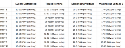
Assuming i have 200 Panels @ 49V each and i have 10 MPPTs with a 600V nominal 1000V max what would be the most ideal distribution of panels to the MPPT ? Assuming the setup listed below are within the amps rating of each mppt.
1705644922693.png

What i want to know is which of these produces me more power per day. Assuming no shading from external object (exempt from maybe clouds).

From what i know and what i read, you want to push as much voltage to the MPPT, because you generate more power that way (Start producing energyy earlier on the day and end later on the day). I also know that you want to use all you mppts available so if there is some shading only that specific string is affected. Is that true or what i know is wrong? If that is true the best setup would be the 20 panel string ('maximing voltage' column). The only thing im worried about that setup is it might be to close to the max voltage of the MPPT, hence i created "maximizing voltage 2".

Typically on the inverter each MPPT has a plug for 2 strings. Are they just literally paralleling the strings inside the inverters? That means i should always balance the number of panels on each string IF im going to use both plugs. I assume that MPPTs should be fine with only one of those plug being used (like in 'maximing voltage' setup)

Also is there a special code for how much amps a PV wire is supposed to handle or are they the same with residential wiring? Im planning on using 8 or 10 AWG @ 1500V (depending on which setup).

what are your thought? which setup should i go for?
 
ohms law hasn't been repealed. Watts in equal watts out. Wire size determines max current in open air, bundle it or in conduit changes the rules.
yes but code regulation usually takes into consideration the insulation material of the wire as well. And so far i have not seen mention of PV type wires on them.

I have actually found another thread about this so that part of the question is answered:
 
Picking these monster numbers (for this DIY forum) I don’t think helps much with intuition. There’s also a lot of large scale system design layers that I have seen practically no mention of on this forum.

When playing in grown up system sizes with tons of degrees of freedom and budget at stake probably need to do more simulation than people on this forum usually do.

From what i know and what i read, you want to push as much voltage to the MPPT, because you generate more power that way (Start producing energyy earlier on the day and end later on the day).
You also reduce wire size/voltage drop.

980V is pretty ill advised because of VOC increase as temperatures decrease. That’s going to be a dead MPPT. The headroom is percentage based as the VOC temperature coefficient is expressed in % and it multiplies across the whole string.

Another consideration is what the nominal voltage of the inverter is, if you keep Vmpp near it you will get closest to advertised efficiency. Some combination of how the design is optimized and minimizing the buck/boost ratio to hit the DC rail voltage of the inverter. Probably in a lot of systems the transmission loss will be comparable to or bigger than this efficiency hunting.

I specifically call out inverter because the buck ratio on a 48V SCC is so high that there likely is not a huge difference in efficiency (they’re all dropping a lot more than ideal).

Typically on the inverter each MPPT has a plug for 2 strings. Are they just literally paralleling the strings inside the inverters? That means i should always balance the number of panels on each string IF im going to use both plugs. I assume that MPPTs should be fine with only one of those plug being used (like in 'maximing voltage' setup)
Not sure what specific config you reference but I will mention a few.

Some MPPT are internally paralleled as you mentioned.

Other MPPT can serve as either independent MPPT (tracker and DC conversion) OR be ganged together to make one big MPPT. So this is fancier/more flexible than just internal paralleling and is electrically a different architecture.
Also is there a special code for how much amps a PV wire is supposed to handle or are they the same with residential wiring? Im planning on using 8 or 10 AWG @ 1500V (depending on which setup).
75C rating / 1.56 = max ISC

For #8 this is straight forward, no exotic edge cases.

For #10 some people say you can exceed 30A for the starting point because the language around 30A limit is for OCPD and no OCPD is needed in many cases with a solar string.

PV in residential setting is mainly for flexibility and weather resistance at the array. Other than that people use THHN or other single conductor.

PV above residential 600V limit is useful for going to higher voltages than other wire types.

There is a special rule about PV wire flexibility (minimum strand count) for this specific use case at the array where moving panels is needed during service.
 
Picking these monster numbers (for this DIY forum) I don’t think helps much with intuition. There’s also a lot of large scale system design layers that I have seen practically no mention of on this forum.

When playing in grown up system sizes with tons of degrees of freedom and budget at stake probably need to do more simulation than people on this forum usually do.

No worries i this is not a real system (yet... maybe someone crazy will ask me to build something this big), im just really curious what proper consideration should be taken for a system as big as this.

980V is pretty ill advised because of VOC increase as temperatures decrease. That’s going to be a dead MPPT. The headroom is percentage based as the VOC temperature coefficient is expressed in % and it multiplies across the whole string.
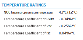
So how do you figure out the required headroom? Id like to get an idea of scale is it 5%-10% or something in the range of 30-45%? How much do temperature affect it, for example areas near the equator doesnt really get cold with the coldest maybe 30 degrees Celsius. I browsed some well known panels datasheet and it did mention some temp coefficient

1705670900510.png

How do i use these percentages? So if i go above 43C the Voc drops by -0.25% and vice versa?

Another consideration is what the nominal voltage of the inverter is, if you keep Vmpp near it you will get closest to advertised efficiency. Some combination of how the design is optimized and minimizing the buck/boost ratio to hit the DC rail voltage of the inverter. Probably in a lot of systems the transmission loss will be comparable to or bigger than this efficiency hunting.

I specifically call out inverter because the buck ratio on a 48V SCC is so high that there likely is not a huge difference in efficiency (they’re all dropping a lot more than ideal).

when you say "nominal voltage of the inverter" which part are you talking about? the output AC voltage? the battery voltage (for hybrids?) ? or the nominal voltage of rating of the panels that the inverter takes?


Not sure what specific config you reference but I will mention a few.

Some MPPT are internally paralleled as you mentioned.

Other MPPT can serve as either independent MPPT (tracker and DC conversion) OR be ganged together to make one big MPPT. So this is fancier/more flexible than just internal paralleling and is electrically a different architecture.

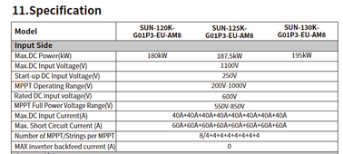
Can this be even easily looked up? I have seen multiple inverter datasheets and manuals but i dont remember seeing information about what their MPPT specifically are. For example if we look up deye's largest inverter 135kw manual. This is really the closest info we can get about their MPPTs

1705670506584.png
 
Last edited:
So how do you figure out the required headroom? Id like to get an idea of scale is it 5%-10% or something in the range of 30-45%? How much do temperature affect it, for example areas near the equator doesnt really get cold with the coldest maybe 30 degrees Celsius. I browsed some well known panels datasheet and it did mention some temp coefficient

View attachment 189837

How do i use these percentages? So if i go above 43C the Voc drops by -0.25% and vice versa?
I like this online calculator for understanding the highest VoC you would see based on the lowest temperatures for the area. https://spheralsolar.com/solar-panel-voltage-calculator/

And yes, the measured VoC actually does go down as temperature increases.
 
I like this online calculator for understanding the highest VoC you would see based on the lowest temperatures for the area. https://spheralsolar.com/solar-panel-voltage-calculator/

And yes, the measured VoC actually does go down as temperature increases.

Thank you for the link. So basically the panels are more efficient when they are cold.

All that remain now is at what Voc should should you size your string is it the highest voltage you can go with respect to temperature or the nominal/rated voltage of the MPPT of the inverter? Assuuming we are using the 135kW growatt example 600V
For that example, I would say shoot for the 600 volts as it looks like that is where it is most efficient, but of course stay under the 1000 volts with your temperature adjusted VoC as that is where going over will physically damage the controller.
 
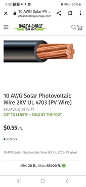
Make ABSOLUTELY sure the wire chosen has a 1KV insulation rating.
Most over 600V is 2KV
Screenshot_20240119_173236_Chrome.jpg
Follow ALL isolation and safety installation rules.
Everything would need proper Voltage safety plackards.
I have a guy near me that laser cuts perfect plackards same day.

As for the max voltage calculator, you input the RECORD COLD TEMP for the area, then fill out the panel specs to thw fields of the calculator, and adjust until max voltage will not exceed the controller's limits, and that is what you size the array strings for.
 
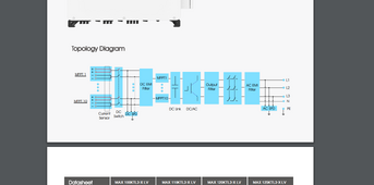
Oh here something that i found Growatt shows their MPPT topology. Where does this belong in what you have said?

Can't tell because it does not say how the MPPTs can be locked with each other via software so that they make coordinated changes when connected to the same string.

Can this be even easily looked up? I have seen multiple inverter datasheets and manuals but i dont remember seeing information about what their MPPT specifically are. For example if we look up deye's largest inverter 135kw manual. This is really the closest info we can get about their MPPTs

I don't know what the standard format is, but I've been able to see the feature in manuals when people ask.

I read the relevant pages of this manual and it has almost no config for the strings, just monitoring. It has all the AC grid parameter settings one might want (through 1741SA requirements if I'm not mistaken).

How do i use these percentages? So if i go above 43C the Voc drops by -0.25% and vice versa?
You make sure to get the Voc / test condition matrix straight. If you want to start from NOCT temperature, use the NOCT VOC. If you use STC Voc but adjust from 43C, you will get the wrong answer (over-estimate if I'm not mistaken)

when you say "nominal voltage of the inverter" which part are you talking about? the output AC voltage? the battery voltage (for hybrids?) ? or the nominal voltage of rating of the panels that the inverter takes?

Spec sheet will list nominal voltage and the ones I've looked at recently correspond to what the HVDC rail should be when generating the operating VAC of the inverter (I said this in my previous post). That is for AIO where the MPPT generally does not have to drop to battery voltage before going to the inverter.

My guess is the inverter you link (for 230/400V wye connected system) wants to see 600V because it is set up to send inverter power from leg to leg, and starting from 600VDC is convenient. It is a grid tie, so not grid forming, so does not benefit from wiring up the inverters from neutral to leg; in that case something around 350V would be
more ideal.
 
Back
Top