diy solar

diy solar

1 EG418KPV: supplying it's multiple mppt inputs from a large SINGLE solar array?

If I meet the kw, volt, and amp limits, can I have multiple strings of panels in series and parallel for each mppt input? Is there some limit on the number of strings? Say 3 or 4 strings paralleled for #1 mppt input , 2 strings in parallel for #2 mppt input, etc, as long as I meet the reqs/limits for the EG418KPV ?
As long as you meet the specs you can have as many strings as you like. Keep in mind that if a single MPPT has more than two strings, each string must be fused.
 
I am not sure about that. Isc and Imp are too close together.
The difference is 6/4/4a.
Fuses would be hard to find.
Electronic OCP would be better.
Personally I wouldn't worry about it. Actually, I haven't been worried about it with my own equipment. If my $600 AIO's can deal with it. Surely something at triple the price should be able to.
 
How easy is it to swap the MPPT board if it gets killed?

Also if it dies in a few years there’s pretty low guarantee you can get the exact parts. No track record from Luxpower/EG4
 
How easy is it to swap the MPPT board if it gets killed?
Couple plugs and screws.
Also if it dies in a few years there’s pretty low guarantee you can get the exact parts. No track record from Luxpower/EG4
That's true for any new product. These days, almost everything is disposable. Companies and customers want to stay on the cutting edge at all times. As soon as the hype starts to diminish, they want to move on to the next popular thing.
 
Clipping means the available DC power exceeds the AC rating, so it will plateau (literally looks like this in the graph) and you lose the production.

Orienting multiple parallel strings in different directions causes them to have peak output at different times of the day, which helps with clipping a lot.

Then there is the electrical safety limit. Max Isc and power levels where reverse polarity protection limit breaks

Yes, sending DC is absolutely better than AC from a power loss angle, and you also likely do not want to put your batteries at the array which is what is needed if you send AC. The inverters also need current sensors in some situations, and those need to be placed close to the load.

OTOH at some point AC becomes easier to mix together than DC, you see a bit of that here in how you can’t connect multiple MPPT to the same array unless they can be locked together.

I would say most AIO and hybrid MPPT would be designed for #8 and #10’s ampacity limit. Standalone MPPT likely go higher.
"The inverters also need current sensors in some situations, and those need to be placed close to the load."

Sounds like something I need to understand, if especially if I supplement the large pasture array with ac power from my trailers' inverters.

Also, I now see thanks to you guys that proper panel orientation to avoid clipping may be essential to making my large pasture array work. I can see how the 3 separate mppt input circuits is good for creating three different panel orientations, maybe a 15 amp "mid morning" array, a 25 amp "noon" array, and a 15 amp "afternoon" array? But what about different panel orientations for my above proposed case of 5 paralleled sets of 11 panel strings? Maybe some controller/inverters could handle the whole array in the same orientation without clipping? Or maybe there are good reasons to have different orientations anyway? I'm just starting to consider this, and which strings, etc. to reorient, and how. Food for thought. Thank you.
 
Current sensors

Sounds like something I need to understand, if especially if I supplement the large pasture array with ac power from my trailers' inverters.

The idea is that you need the current sensors placed in the right place to allow the hybrid inverter to know how much output power to emit from the battery or direct from PV, so as to zero-out (or get as close as possible to it) the input power from the grid. If you only use sensors internal to the inverter, it can only detect the demand from the loads connected to the inverter via the critical loads AC output OR dump the battery/solar out to grid at full power (only desirable if you have 1:1 net metering or there's nowhere else for the power to go anyway).

One place where it tends to work is to put the remote CT sensors right after the service disconnect. This guarantees that the hybrid and the loads are on the same side of the CTs as the grid. If the loads are < current hybrid AC output level, then the CTs will read that there's power being drawn from the grid, so the hybrid AC output should ramp up. After matching the CTs (ie zero net power), if loads turn off then the CT will read that there's excess AC output being sent, and the AC output will wind down.

If there is a surge load the CTs will still read import from grid, but there's not much the AC output can do at that point b/c it's out of headroom. You're still saving money though. You can use data from an energy meter or utility bill to see how frequently you hit this condition. You can install multiple energy meters to gather this information at different points in your electrical distribution, if there are only some places you can readily install CT sensors.

If you buy a high end hybrid like EG4 18kpv or SolArk 15k, and insert it between service disconnect and up to 200A of loads, then everything is taken care of for you without external CTs (assuming it has both internal and external, if it only has one set then you still need to install CTs, they just can be right next to the hybrid).

If you have a large property, you probably want to use an inverter with the option to use a serial bus CT sensor/energy meter, since this gives you more wiring options to collect data over long distance (EG if you have a really long run to do you can theoretically convert to fiber and pull that. Not sure what the distance is on the best quality twisted pair). Theretically a serial bus system can also do a better job of handling sensors in multiple points if needed, however this is a more advanced kind of install.

Different orientation helps:

(1) spread the production around the day, which is definitely good for those of us without storage that are selling back to grid. It is also potentially good for reducing the amount of battery power you need. Dunno if there is a good optimizer for this.

(2) helps save some money on the MPPT / wiring

Note that code still requires the wiring to be able to handle the full output of the strings, extra relevant if you parallel at the array side. There are some situations like specific cloud patterns where sun will bounce in from multiple directions.
 
I did not finely read the entire thread.
55 panels at 365 watts = 20,075 watts. This accepts 18,000 watts of PV.
The Voc of panel is 44.6, The short circuit current is 10.19 amps. Connecting to MPPT 1: 10 panels in series to PV1 "A" would be 3650 watts. 10 panels to PV1 "B" would be another 3650 watts. MPPT 2: 10 panels in series would be 3650 watts. MPPT3: 10 panels in series would be 3650 watts.

MPPT 1 would have ~20.2 amps @ 446 volts, max amperage is 25. MPPT 2 would have 10.2 amps at 446 volts. MPPT 3 would have same as MPPT 2. Amp limit of MPPT and 3 is 15 amps. MPPT 1 should all face in the same direction. MPPT 2 and 3 can face independently from MPPT 1 and each other.

I think if you add more panels in series, you may exceed safe Voc. Same if you try to parallel a string and add amperage. But your choice.

Wire can be 10 AWG solar PV wire, 600 volts DC or 1000 Volts DC.

Apply wire ferrules to stripped ends of PV wires when connecting to the inverter.

The additional solution would be to add a separate stand alone charger to your remaining 15 panels to be added to what is built into the inverter. Like an Outback Flexmax 100.
 
The idea is that you need the current sensors placed in the right place to allow the hybrid inverter to know how much output power to emit from the battery or direct from PV, so as to zero-out (or get as close as possible to it) the input power from the grid. If you only use sensors internal to the inverter, it can only detect the demand from the loads connected to the inverter via the critical loads AC output OR dump the battery/solar out to grid at full power (only desirable if you have 1:1 net metering or there's nowhere else for the power to go anyway).

One place where it tends to work is to put the remote CT sensors right after the service disconnect. This guarantees that the hybrid and the loads are on the same side of the CTs as the grid. If the loads are < current hybrid AC output level, then the CTs will read that there's power being drawn from the grid, so the hybrid AC output should ramp up. After matching the CTs (ie zero net power), if loads turn off then the CT will read that there's excess AC output being sent, and the AC output will wind down.

If there is a surge load the CTs will still read import from grid, but there's not much the AC output can do at that point b/c it's out of headroom. You're still saving money though. You can use data from an energy meter or utility bill to see how frequently you hit this condition. You can install multiple energy meters to gather this information at different points in your electrical distribution, if there are only some places you can readily install CT sensors.

If you buy a high end hybrid like EG4 18kpv or SolArk 15k, and insert it between service disconnect and up to 200A of loads, then everything is taken care of for you without external CTs (assuming it has both internal and external, if it only has one set then you still need to install CTs, they just can be right next to the hybrid).

If you have a large property, you probably want to use an inverter with the option to use a serial bus CT sensor/energy meter, since this gives you more wiring options to collect data over long distance (EG if you have a really long run to do you can theoretically convert to fiber and pull that. Not sure what the distance is on the best quality twisted pair). Theretically a serial bus system can also do a better job of handling sensors in multiple points if needed, however this is a more advanced kind of install.


(1) spread the production around the day, which is definitely good for those of us without storage that are selling back to grid. It is also potentially good for reducing the amount of battery power you need. Dunno if there is a good optimizer for this.

(2) helps save some money on the MPPT / wiring

Note that code still requires the wiring to be able to handle the full output of the strings, extra relevant if you parallel at the array side. There are some situations like specific cloud patterns where sun will bounce in from multiple directions.

Hi , sorry for the delayed response. This stuff is going to take a while for me to understand.

If you only use sensors internal to the inverter, it can only detect the demand from the loads connected to the inverter via the critical loads AC output OR dump the battery/solar out to grid at full power (only desirable if you have 1:1 net metering or there's nowhere else for the power to go anyway).

My system is ultimately going to have to pass muster I'm sure at some point with the local electric "cooperative." Most people around here, by the way, seem to be negative on solar: it's rural eastern North Carolina. There's no net metering here. I need the best system to protect against it ever back feeding power to the grid, which will be their only legitimate argument. (Yes, I will definitely go to court over this, if it comes to it. I will discuss with a lawyer in depth and prepare well before install and people start talking). I need to understand the tech best I can first, for multiple reasons.

One place where it tends to work is to put the remote CT sensors right after the service disconnect. This guarantees that the hybrid and the loads are on the same side of the CTs as the grid.

The service disconnect is where the power company would shut off my power for failure to pay bills, for example, correct? So "right after" is downstream toward my house, and that would put the current sensor (CT) on the OPPOSITE side of the service disconnect as the grid, correct? And does the hybrid come next, right after the CT, but before my main breaker? Thanks.

If you buy a high end hybrid like...
I will. But still want to understand what you say concerning CT placement concept.

If you have a large property, you probably want to use an inverter with the option to use a serial bus CT sensor/energy meter,

Food for thought. Regarding having different panel orientation,

(1) spread the production around the day, which is definitely good for those of us without storage that are selling back to grid. It is also potentially good for reducing the amount of battery power you need. Dunno if there is a good optimizer for this.

Makes sense. "Optimizer?"

Note that code still requires the wiring to be able to handle the full output of the strings, extra relevant if you parallel at the array side. There are some situations like specific cloud patterns where sun will bounce in from multiple directions.
Planning currently to parallel 5 strings of 11 panels each, if it makes sense. See below, my response to glandpuck...

There are some situations like specific cloud patterns where sun will bounce in from multiple directions.
You mean, cloud patterns that still cause clipping, even with differently oriented "sub arrays" of panels all going into one hybrid? Thanks, I really appreciate the help zany!
 
Last edited:
I did not finely read the entire thread.
55 panels at 365 watts = 20,075 watts. This accepts 18,000 watts of PV.
The Voc of panel is 44.6, The short circuit current is 10.19 amps. Connecting to MPPT 1: 10 panels in series to PV1 "A" would be 3650 watts. 10 panels to PV1 "B" would be another 3650 watts. MPPT 2: 10 panels in series would be 3650 watts. MPPT3: 10 panels in series would be 3650 watts.

MPPT 1 would have ~20.2 amps @ 446 volts, max amperage is 25. MPPT 2 would have 10.2 amps at 446 volts. MPPT 3 would have same as MPPT 2. Amp limit of MPPT and 3 is 15 amps. MPPT 1 should all face in the same direction. MPPT 2 and 3 can face independently from MPPT 1 and each other.

I think if you add more panels in series, you may exceed safe Voc. Same if you try to parallel a string and add amperage. But your choice.

Wire can be 10 AWG solar PV wire, 600 volts DC or 1000 Volts DC.

Apply wire ferrules to stripped ends of PV wires when connecting to the inverter.

The additional solution would be to add a separate stand alone charger to your remaining 15 panels to be added to what is built into the inverter. Like an Outback Flexmax 100.
Label from one of the 8 actual panels below I bought several years ago says Voc 44.3.

54 just-purchased Rec365AAs are in transit to me. I bought two more Rec365AAs I'm gonna pick up soon. They should all surly be the same, although some spec sheets covering multiple REC3XXAA models (355 360 365 370 375) say Voc is 44. I'll do the math again. I'm not worried about having too many panels. I have two trailer to put them on and eventually I'm gonna build a vacation house. I still need to figure my probable loads for my house in question. There is a propane backup generator that's 34 KW, if that tells you anything. (I keep this propane hog off all the time, even when the power frequently goes out! ). The main house is long and narrow, with three separate HVAC systems! There is a large outbuilding also with its own HVAC. Summer in coastal NC is hot, and that's where the potential for big usage comes in. The systems are from the early 90s and are absolute electricity hogs to cool. I'm gonna put in some mini splits (EG4 | Hybrid AC/DC Solar Mini Splits), but it's still nice to have the hogs if I can feed them, or some of them, for quicker cool downs of the house/outbuilding, perhaps. By the way, I have plans to be able to use a lot more energy than that when the sun is shining, from huge greehouse heating and cooling to non lithium energy storage for overnight/cloudy days, but that's a topic for another day and another thread, as far as I'm concerned. Thank you!

edit: ps, I plan on having a lot of lithium phosphate battery storage too.
 

Attachments

  • rec label.jpg
    rec label.jpg
    103.5 KB · Views: 3
Last edited:
I need the best system to protect against it ever back feeding power to the grid, which will be their only legitimate argument. (Yes, I will definitely go to court over this, if it comes to it. I will discuss with a lawyer in depth and prepare well before install and people start talking).
Do they not have the equivalent of what we call Rule21 in California, which is the full set of utility regulations? AFAICT there should be existing non solar cases that are regulated, for instance backup generators that are always spinning in idle, running parallel to grid. Or on-site cogeneration power plants.

Did you try looking at Greenlancer or plans company? Someone might have done a project in your state / POCO.

The service disconnect is where the power company would shut off my power for failure to pay bills, for example, correct? So "right after" is downstream toward my house, and that would put the current sensor (CT) on the OPPOSITE side of the service disconnect as the grid, correct? And does the hybrid come next, right after the CT, but before my main breaker? Thanks.
POCO will pull at meter or send shutoff command to meter.

The service disconnect is often your first breaker past the meter. It is where the N-G bond is made. Anyway it doesn’t, the service disconnect, as long as it is able to see the full load that you want to offset, such that increased output from the hybrid will reduce the reading. AND it is placed within customer owned equipment.

That order sounds about right, I’ve unfortunately forgotten the full context of the thread.

Makes sense. "Optimizer?"
Design optimization software

You mean, cloud patterns that still cause clipping, even with differently oriented "sub arrays" of panels all going into one hybrid? Thanks, I really appreciate the help zany!

Imaging a situation where there is a ring of fluffy bright clouds at a distance. This can boost the output of a single array pretty high since sun is coming from more angles. This also helps the different oriented arrays
 
Do they not have the equivalent of what we call Rule21 in California, which is the full set of utility regulations? AFAICT there should be existing non solar cases that are regulated, for instance backup generators that are always spinning in idle, running parallel to grid. Or on-site cogeneration power plants.
I don't know I will look into it thoroughly though. Lots of Generacs here, that's for sure. The anti-solar attitude is, well... interesting, to say the least, and , around here, the less I say about and focus on that attitude, the better! Safety of electric crews is of course a totally legitimate concern
The service disconnect is often your first breaker past the meter. It is where the N-G bond is made. Anyway it doesn’t, the service disconnect, as long as it is able to see the full load that you want to offset, such that increased output from the hybrid will reduce the reading.
"...as long as it is able to see the full load that you want to offset, such that increased output from the hybrid will reduce the reading."

Right. And I want to be able to have the solar panels/batteries connected to power every load I have, all 4 HVAC systems, pumps, shops, greenhouses, etc. Basically everything off my main breaker. And IF I choose to disconnect from the grid completely sometimes, it will be up to me not to turn on every HVAC system, etc., at the same time. Thoughts?

That order sounds about right, I’ve unfortunately forgotten the full context of the thread.
I think I got the order wrong. Of course I will ultimately have a professional consultant/installer on site review and sign off on the work, but I need to and would like to understand. I actually can't readily conceptualize how the hybrid ties into a grid tie system I envision where I never give power back to the grid, but the grid is there for me when I need it/want as a supplement or substitute. I just can't see it.

Furthermore, and possibly more complicating, like I said, I'd like to be able to physically cut off the grid power, whenever I want. I know I can change the setting on the hybrid so it takes no power from the grid, but a physical switch sounds appealing to be sure about actually being off grid. 
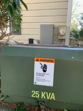
But back to my main confusion: for my envisioned "grid tie," how can the hybrid charger/inverter be placed anywhere except between the utility's power meter at my house and my house's transformer? So, it must be upstream of the utility meter, and downstream of the house transformer, right? See attached pic, the transformer says 25 KWA, and there's plenty of room b/w it and the meter. The old Generac propane hog at the house is 34 kw, I'm pretty sure. It was here when I moved in.
=======
Imaging a situation where there is a ring of fluffy bright clouds at a distance. This can boost the output of a single array pretty high since sun is coming from more angles. This also helps the different oriented arrays
It's interesting, and I'm glad to know about having sub-arrays going to separate mppt inputs on the hybrid, or just one mppt input with some strings with different orientations. I was aware of "clipping" in audio recording, but before this forum made me aware of it in the solar context, I thought it would be a great benefit to have panels placed right beside and due north a large lake or body of water so that the intense reflection in winter of the low sun bouncing off the often smooth as glass water into the solar panels would nearly DOUBLE the amount of light reaching at times. But this seems in fact a terrible liability! It appears to make it extremely difficult to size the system properly, and use panels economically! I am indeed on the water, but I can place the solar panels far enough away from the water to avoid this. I previously wished I had enough room to place them on the water for this very reason! I was planning on putting my two trailers to be covered with solar panels on the water. Yikes! RVers must have a hard time with this in winter, right on the water. I wonder if a lot of these RVers' systems get overloaded?

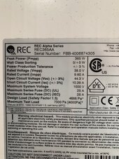
Thank you so much zany and the forum. What a great resource. I've wanted solar/wind since I started RVing around 2000. True off-grid independence potential. The dream is finally starting to materialize (I took delivery today of 16 LiTime LiFePO4 230ah today! 54 REC365AAs on the way and I have ten already.)

I started watching Will's videos occasionally several years ago. He explains things so well for novices like me, and he really breaks things down (sometimes literally!). But it's his personality that makes him is the best ambassador for solar imaginable. I got a still-boxed 24k BTU EG4HybridAC/DCSolarMiniSplit because of him, and plan to get more eventually, and same goes for LiTime LiFePO4. I know he has affiliations with some of these products, and I do my own homework, just like I'm doing here with the EG418KPV, but I've gotta say I just trust this guy, and that's really not something I say often in a business context. An example of my homework is something I've become aware of that, if true, is potentially important in the marine context. Evidently, lithium batteries above 100-200ah should NEVER be used on boats that will ever be in rough water, even big yachts. And 100ah is much preferable! It's a matter of the cells losing physical integrity and structrual strength as the size of the cells are scaled up. I was aware of this possibility when I pulled the trigger on the 16 LiTime 230ah, for home and RV/trailer use, but I plan for a battery bank of 100 ah batteries for the marine purpose. And EG4 had their 100ah batteries of sale a few weeks ago for about $235 each! But I think the LiTime LiFePO4 100ah trolling batteries are even better for this purpose. I think Will does too, but that's conjecture. He's says he's never see such surge power. Thanks forum!
 

Attachments

  • transformer&meter.jpg
    transformer&meter.jpg
    143.4 KB · Views: 2
Last edited:
Lots of Generacs here, that's for sure.
Generacs are probably start on demand. So they would be on much easier regulatory scheme.

Cogeneration generators are generators in factories that provide both thermal and shaft power/electrical and are always running. They can be synchronized and interconnected to grid. I’m sure this has been sorted out between the factory owners and the utilities.

Zero export solar is basically the same effect on the grid. The main difference in California is that they don’t force you to pay as much in engineering and application fees to connect your small house system, as compared to a factory’s system

Right. And I want to be able to have the solar panels/batteries connected to power every load I have, all 4 HVAC systems, pumps, shops, greenhouses, etc. Basically everything off my main breaker. And IF I choose to disconnect from the grid completely sometimes, it will be up to me not to turn on every
You need everything you want running downstream of the point that remains active when grid goes down. You can use some automation to help like smart breakers or relays. The solution for generators will not necessarily work for solar since a lot of the generator type sense when the generator is about to seize up from being overloaded. That doesn’t happen for solar, it just dies.

intense reflection in winter of the low sun bouncing off the often smooth as glass water into the solar panels would nearly DOUBLE the amount of light reaching at times. But this seems in fact a terrible liability!
I think this is fine. It’s similar to bifacial optimization, with a similar pitfall in terms of how to properly scale up the output numbers for safety calculations. Since NEC is not super prescriptive about bifacial gain calculations at this point it’s probably not a major safety issue up to this point, to where someone raises noise at the code update meetings.

Even with clipping you’re still producing more, just not as much more as when you don’t clip.
 
I sure appreciate the help zany.
Right. And I want to be able to have the solar panels/batteries connected to power every load I have, all 4 HVAC systems, pumps, shops, greenhouses, etc. Basically everything off my main breaker. And IF I choose to disconnect from the grid completely sometimes, it will be up to me not to turn on every

You need everything you want running downstream of the point that remains active when grid goes down.

"...of the point that remains active?" No comprendo, sorry. I want to be able to solar power everything downstream of my main breaker. My main breaker turns off everything: the house, guest house, well pump, etc., everything.

I think this is fine. It’s similar to bifacial optimization, with a similar pitfall in terms of how to properly scale up the output numbers for safety calculations. Since NEC is not super prescriptive about bifacial gain calculations at this point it’s probably not a major safety issue up to this point, to where someone raises noise at the code update meetings.

Even with clipping you’re still producing more, just not as much more as when you don’t clip.
So, glass-like water between south facing solar panels and the sun December 20/21st won't overload the hybrid charger/inverter ? I guess the panels limit their own input and output to their specs? I'm almost certain there's nearly double the photons at times because of the reflection, but, then again, it's during winter, when the sun is low and weaker. It's not like doubling the summer sun. Would the panels limit their own input and output in the case of using mirrors to double the summer sun's rays, I wonder?

Thanks forum.
 
"...of the point that remains active?" No comprendo, sorry. I want to be able to solar power everything downstream of my main breaker. My main breaker turns off everything: the house, guest house, well pump, etc., everything.
You want everything you want running after the regular output of the EG4 18kpv.

If you have stuff you want disconnected when running off-grid, you can put them on generator "input". It's more of a "configurable input/output". However if you want to connect a generator then this generator input might already be used.

So, glass-like water between south facing solar panels and the sun December 20/21st won't overload the hybrid charger/inverter ? I guess the panels limit their own input and output to their specs? I'm almost certain there's nearly double the photons at times because of the reflection, but, then again, it's during winter, when the sun is low and weaker. It's not like doubling the summer sun. Would the panels limit their own input and output in the case of using mirrors to double the summer sun's rays, I wonder?

Panels don't limit the output to their specs. If you take a solar panel and shoot it in space inward to a place closer to the sun, it will definitely output more than the nameplate. Same with putting them in a sunny, high altitude location, subjecting them to cloud lensing (fancy term for weather conditions that magnify the irradiance above what you can see on a sunny day), or using them in some kind of mirror solar concentrating setup.

This is why NEC has you add a 25% safety factor for solar panels for most types of panels. And you're also supposed to add more for bifacial (which can take sun from the back side, similar to you increasing front side irradiance with the pond). But it doesn't (as of today, though I haven't read 2023 revision in this area) say HOW MUCH to add for these other cases. If you think it's mostly around the time when sun is low anyway, then there is no code authority / standard advice telling you to do otherwise.
 
Back
Top