diy solar

diy solar

How do you tell if you batteries and inverter are working at their peak

ardy564

New Member
Joined
Jul 6, 2023
Messages
8
Location
23966
correctly. I have a 3000W inverter and 3 x 100AH of lithium batteries. The manufacturer of the inverter says the minimum for 3000W is 3 batteries, yet I'm not sure if I am getting 100% out of either. When I run my shop VAC or Portable AC (not together) the inverter cycles off and then back on without fault codes or tripping the breaker. My assumption is that the BMS on the batteries are shutting them down. These are generic batteries with a generic BMS which means I'm probably not getting the most amperage out of the batteries. I've order a forth to see if the problem gets better.

Any advice or troubleshooting tips would be appreciated.
 
Check ALL your connections. Most likely you have a loose connection or a bad crimp or too-thin of cable. Do you have a DC amp clamp meter?

Now if you happen to be pulling all 3000W from the inverter (many cheap inverters blatantly lie about their output):

3000w/12.8v/0.85 = 275A. Assuming your 3 x 100Ah are 12v batteries wired in parallel, you'd be pulling about 275A, could be more if there's a lot of resistance in the cabling. Very easy for you to have not-top-notch cabling or connections or both and be maxing out what the BMS's can produce (up to 300A).

What brand and model of batteries? Brand and model of inverter. List of specs or links are helpful.

Even more helpful are photos of your wiring.
 
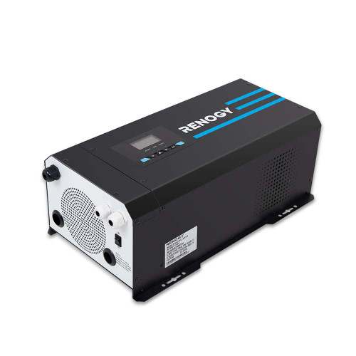
Inverter is RENOGY 3000W Charger/Inverter.
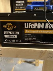
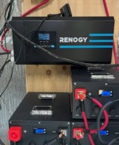
Batteries see image. Batteries are wired in parallel with 2awg battery cables. See image #2 not the best.


IMG_3428.jpegIMG_3416.jpeg
 
2awg wire is rated for about 115 amps (depending on the insulation). Is the wire from the batteries to the inverter 2awg or 3/0 or 4/0 awg wire. (My Victron 12/3000 calls for 4/0 wire).

If all the battery wires are 2 awg you could have the problem where the first battery is able to give its all(100amps) but the wire from the first to the second battery cannot transfer 200amps only about 115 - so the second battery gives say 80 amps and the third only about 35 amps - all due to the wire.

I would get a good (copper) bus bar and connect each battery to the bus bar with the 2awg wire (all the Cables need to be the same length). Then from the bus bar to the inverter the cable probably should be 3/0 or 4/0.
 
Can't really tell from your photos, but if you only have 2AWG between inverter and batteries, that could be your problem. 2AWG is only good for up to 115A (a bit more with better insulation on the wire). While 2AWG is fine for between each of the batteries, 2AWG is woefully inadequate for your inverter cables AND your batteries in parallel (Thanks @Rocketman for the correction).

I would recommend at least 2/0 AWG cables rated for 330A, but 4/0 AWG would be my goto, as this cabling is good for up to 445A.

The 4/0 would be best because it will really help a lot with reducing voltage sagging, which can cause a ton of problems and make your inverter angry.

Trust me on this. I just upgraded my solar system and one of things I did was go beefier on the cables for a 12v system and the system doesn't have the same voltage drop problems it once had.
 
One tool that can help in multiple ways is a Victron shunt (Smartshunt or BMV712).

You will know how full or empty the batteries are.
You can know how many amps/watts are entering or leaving the battery.
When their is a problem- you can go back on the graphs and see was going on with the voltage and current.
 
2awg wire is rated for about 115 amps (depending on the insulation). Is the wire from the batteries to the inverter 2awg or 3/0 or 4/0 awg wire. (My Victron 12/3000 calls for 4/0 wire).

If all the battery wires are 2 awg you could have the problem where the first battery is able to give its all(100amps) but the wire from the first to the second battery cannot transfer 200amps only about 115 - so the second battery gives say 80 amps and the third only about 35 amps - all due to the wire.

I would get a good (copper) bus bar and connect each battery to the bus bar with the 2awg wire (all the Cables need to be the same length). Then from the bus bar to the inverter the cable probably should be 3/0 or 4/0.
Thanks for the input. I will up the connection gauge and use the buss bar idea.
 
They recommend 4/0 wire
That they do. I mis-read their recommendation. Putting together the component list now. At least my instincts were correct in that something wasn’t adding up.
 
So I've upgraded the cabling to 4/0 battery cable. That is an expensive mistake. Any one need 2 AWG battery cables? :)
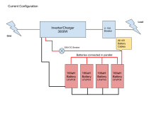
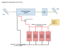
So now my next question based on post comments is this... What are the advantages of BUSBAR vs POST TO POST on the batteries? I've include some images to visualize things. Current Configuration.pngSuggested Configuration.png
 
Both drawings are good.

There are several advantages of a bus bar design:
1. While you want 4/0 cables from the bus bar to inverter, from each battery to bus bar can be smaller cables. Must use all same size and length of cables. (Maybe too late for you now…)
2 the current draws and charging will not be completely equal in the first drawing- they will be very close. I do not know exactly why, I believe it is a small percentage. Just the difference of going from good to great.
3. Serviceable- if in the future you need to service one battery- it is very easy to pull one out and work on it.

There may be more.
I thought about the charger. I went with + on battery 4 and - on battery one thinking this would balance the charging. Am I wrong in my thinking?

So I could use 2awg cables from battery to busbar? I thought I would need the same from batteries to busbar.
 
Yes from batteries to busbar - you could use 2awg - as long as all the cables from batteries to bus bar is the same - length,size,etc.

Yes the way you connected the wires to battery #1 & #4 is a very good way of doing it. If you are not using a busbar that’s what is recommended. I “think” it does balance out almost all the charging and discharging, but the experts recommend bus bars. -sorry above my knowledge-

But the real experts say it is better to use busbars. See wiring unlimited.
 

diy solar

diy solar
Back
Top