You are using an out of date browser. It may not display this or other websites correctly.
You should upgrade or use an alternative browser.
You should upgrade or use an alternative browser.
How to connect a switch on overkillsolar BMS
- Thread starter missoo
- Start date
Ampster
Renewable Energy Hobbyist
That means there will still be some consumption by the BMS. AFAIK, it is small and only significant if the batteries are left unattended for a long period.NOTE: The auxiliary switch will ONLY turn off discharging, not the charging, as I just learned.
Hi everybody,
I just plugged my solar pannel. I turned on the BMS switch, and the light on my RV turned on (which is normal I didn't install a switch yet for the light).
However, when I turned off my BMS switch the light stayed on. It seems that the loads were still supplied by the battery.
When I tried my BMS switch without my solar panels it was working normally (the light went off when the switch was off).
Could you tell me what is happening ?
Horsefly
Solar Wizard
Sounds like the solar is powering your lights, with the battery power disabled because of the BMS discharge being off. So I don't think the loads are being powered by the battery.
MisterSandals
Participation Medalist
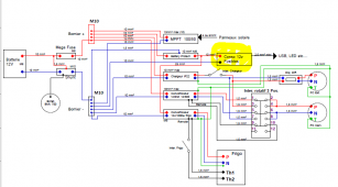
Can you explain/show how you have this wired?Isn't it weird that the solar is powering my lights (and other loads by the way) ?
MisterSandals
Participation Medalist
Assuming your BMS is part of your batterie, the BMS has no way of disconnecting other power sources from your copper bus bars.
Your chargeur IP22 would also power your bus bars with the BMS turned off (probably as designed/desired).
Your chargeur IP22 would also power your bus bars with the BMS turned off (probably as designed/desired).
So when the BMS is off, the solar panels and the solar charge controller are still charging my battery. However as I am not using the loads output of my epever charge controller, how can the lights be on ?
I have a separate switch for the victron battery charger and the victron inverter.
I have a separate switch for the victron battery charger and the victron inverter.
MisterSandals
Participation Medalist
If it performs as Topper's does, then yes. It should be easy to test and confirm.So when the BMS is off, the solar panels and the solar charge controller are still charging my battery.
Your MPPT and IP22 charger power the bus bars that your lights are connected to.However as I am not using the loads output of my epever charge controller, how can the lights be on ?
I do not see a distinction between the connections of your MPPT(epever) to the bus bars. Your drawing shows a single line for positive and negative. A more detailed diagram showing charge wires and load wires would possibly answer that question.
What is Topper ? ....
You are right, the mppt is directly connected on the copper bus bar. I had no idea that without using the "load output" it could power my consummers/loads which are all connected to the bus bar as well.
The IP22 was turned off when I noticed the light was on while the BMS was off. I guess it's coming from my MPPT.
All the loads are connected here together.
Do you need more informations ?
Do you think something is wrong with this wiring ?

MisterSandals
Participation Medalist
What is Topper ? ....
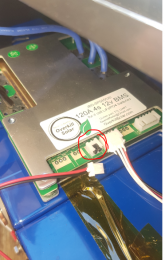
Remove the little black jumper and plug in the pigtail lead.
NOTE: The auxiliary switch will ONLY turn off discharging, not the charging, as I just learned.
MisterSandals
Participation Medalist
"Wrong", no.Do you think something is wrong with this wiring ?
I like to keep charging circuits separate from load circuits as much as possible. As drawn, you do not have a fuse between the bus bar and your inverter. The bus bar can be powered by battery (fused), MPPT (unfused) or IP22 charger (unfused).
I also think the SCC load outputs are generally intended for small loads rather than general power supply. Why put load stress on your MPPT when batteries do this work nearly effortlessly?
oh ok yes I did exactly what Topper said ! I also added a switch as described in the overkill solar manual.
So you think I should add a fuse between the bus bar and the inverter ?
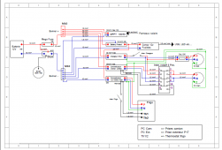
Somebody shared me this diagram that I modified (just a little bit) for my use. As I had no knowledge in electricity I trusted this person.
Sorry I don't know what are SCC load outputs.
What do you mean exactly ? I am not sure I understand.
Do you have any suggestions to improve the system (without too much work, I already spent a lot of time wiring things like that !) ?
So you think I should add a fuse between the bus bar and the inverter ?
Somebody shared me this diagram that I modified (just a little bit) for my use. As I had no knowledge in electricity I trusted this person.
Sorry I don't know what are SCC load outputs.
Why put load stress on your MPPT when batteries do this work nearly effortlessly?
What do you mean exactly ? I am not sure I understand.
Do you have any suggestions to improve the system (without too much work, I already spent a lot of time wiring things like that !) ?
MisterSandals
Participation Medalist
Solar charge controller (your epever MPPT) output/load.Sorry I don't know what are SCC load outputs.
Yes it needs to be fused to be safe.So you think I should add a fuse between the bus bar and the inverter ?
I would move the positive charge wires from the MPPT and IP22 to the battery side of the mega fuse. Fuse to 500w inverter (500/12.8 x 1.25 =) ~50a fuse. Fuse to 1000w inverter (1000/12.5 x 1.25=) ~100a fuse.Do you have any suggestions to improve the system
I would not use the MPPT load outputs.
I would put a breaker (or switch and fuse) between solar panels and MPPT.
Last edited:
Similar threads
- Replies
- 7
- Views
- 258
- Replies
- 2
- Views
- 148


