diy solar

diy solar

How to correctly calculate Voltage Drop between PV array and Battery Bank

Dzl

Unofficial Forum Librarian & Perpetual Newbie
Staff member
Moderator
Joined
Dec 10, 2019
Messages
5,108
Location
West of the rockies
I'm trying to understand how to calculate voltage drop from a PV panel to a battery bank.

I'm getting confused what the 'round trip distance' would be. How do you calculate Vdrop between a PV array and Battery?

examp.png
 
What is your end reasoning?

I dont think it is possible to calculate based on your setup.

The SCC is going to clip whatever volts comes in from the panels to your battery charge voltage. weather it be 100V or 24 volts.

Are you trying to calculate loss from wires?
 
What is your end reasoning?

I'm just trying to make sure my wires are properly sized and my losses are kept to a minimum.

I dont think it is possible to calculate based on your setup.

So I would calculate vdrop for A+B (Panel pos--> SCC --> Panel neg) and then separately calculate vdrop for C+D (SCC pos --> batt --> SCC neg) and the add the two %'s together?

Are you trying to calculate loss from wires?

Exactly. What that's a big part of it at least. I also am just trying to wrap my head around how to calculate Vdrop in circuit that isn't a simple power source --> + wire --> load --> neg wire setup.
 
I'm trying to understand how to calculate voltage drop from a PV panel to a battery bank.

I'm getting confused what the 'round trip distance' would be. How do you calculate Vdrop between a PV array and Battery?

View attachment 9946
I would look at your diagram as two separate circuits.

Circuit 1 SCC<->PV.
For this you would use the resistance of the wire A+B and the current on the circuit.

Edit: Corrected this
Circuit 2 SCC <-> Batt.
For this you would use the resistance of the wire C+D and the current on the circuit.

Notes
1) depending on the type of SCC, the current on circuit 1 could be very different than the current on circuit 2.

2) In both circuits, the voltage drop will vary from nothing when the batteries are charged and no current is flowing to a max voltage drop when the batteries are being charged and the panels are in mid-day sun.
 
Last edited:
There is a formula for what it should be from wire size and length.
I would just measure at the panels and then at SCC to see actual drop.

I think it will vary though based on the load being created from charging so you would probably need that in calculation as well.
 
BTW.... To calculate the drop in one of the circuits, use Ohms law V=I*R
V= Voltage drop in volts
I = Current in amps
R = Resistance in Ohms

You will have to look up the resistance per foot (or meter) of the wire gauge you are using.
 
Here is a link to a voltage calculator I've used. Note that in this calculator, only one-way distance is used, not round-trip.

So, in your drawing, you'd first determine what the drop for the "A" line is, then determine what the drop for the C line would be. Most likely the C-D lines will need larger wires because the charge controller would transform the panel voltage to a lower battery charging voltage, with a corresponding increase in amperage.
 
Note that in this calculator, only one-way distance is used, not round-trip.

That means it does not give the full voltage drop. You must calculate for the round trip to get the correct answer.

Just use the round trip length in the calculator and you will get the full voltage drop. The other way to do it is to calculate each leg of the circuit and add them up.
 
I would look at your diagram as two separate circuits.

Circuit 1 SCC<->PV.
For this you would use the resistance of the wire A+B and the current on the circuit.

Circuit 2 SCC <-> Batt.
For this you would use the resistance of the wire A+B and the current on the circuit.

This was my presumption (in terms of the best way to calculate wire size and Vdrop), but if I do things this way, where I get confused is how to figure out the Vdrop/losses for the total circuit.

Once I've calculated Vdrop for circuit 1 and Vdrop for circuit 2, how do I figure out what my overall losses are between the panel and the battery? Is it as simple as circuit 1 Vdrop% + circuit 2 Vdrop%?

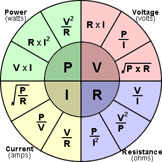
To calculate loss, you should be figuring out the Wattage loss. (Voltage drop is only part of the total loss equation)
Power = Voltage*Current. (Watts Law)
Voltage=Current*Resistance (Ohms Law)

A bit of algebra and we get Line Loss in watts
Power =Current^2 * Resistance.
Notice that the current is squared. That is why high voltage is more efficient. If you double the voltage and halve the current you divide the line loss by 4!

To calculate loss between the Panels and the SCC, figure out the resistance of A+B and multiply it by current squared.
To calculate loss between the the SCC and the battery, figure out the resistance of A+B and multiply it by current squared.

However, if you have properly sized your wires, the line loss will be small compared to the loss in the SCC. Unfortunately, there is not formula for calculating the loss in the SCC. All you can do is go by what the manufacture says the efficiency is (if they say at all).
 
Also, if you're lazy (or lets say smart about managing your time...):

ohms-law-formula-wheel.png
 
Okay I'll take a swing at it.
Assuming 10AWG wire, and assuming A+B is 10ft round trip and C+D is 10ft round trip, and assuming PV output is 1000W @ 100v and SCC output voltage is 24v:

Calculating Voltage Drop
V= I x R

Leg 1:
Vdrop = 10A x 0.00098 x 10ft = 0.1V
Vdrop % = 0.1V / 100V = 0.1% Vdrop

Leg 2:
Vdrop = 41.67A x 0.00098 x 10ft = 0.41V
Vdrop % = 0.41V / 24V = 1.71% Vdrop

Total Vdrop = 0.51V
Total Vdrop % = not a valid/useful metric in a multi voltage system(?)

Calculating Line (Power) Loss:
P=R x I^2

Leg 1:
P=0.00098 x 10^2 = .098 W/ft = 1 watt over 10 feet

Leg 2:
P=0.00098 x 41.667^2 = 1.7 W/ft = 17 watts over 10 feet

Total line loss in watts = 17W + 1W = 18W
Total line loss as a % of power output = 18W / 1000W = 1.8%
 
That means it does not give the full voltage drop. You must calculate for the round trip to get the correct answer.

Just use the round trip length in the calculator and you will get the full voltage drop. The other way to do it is to calculate each leg of the circuit and add them up.
No, what I believe is that the round trip calculation is built into their formula, and the one-way measurement is simply for simplicity.
 
No, what I believe is that the round trip calculation is built into their formula, and the one-way measurement is simply for simplicity.

That is less than ideal. Calculators based on total distance take all the guesswork out of it and are very simple. One way calculators that calculate round trip, have to make assumptions which may or may not be accurate, and can be confusing or misleading.
 
I'm trying to understand how to calculate voltage drop from a PV panel to a battery bank.

I'm getting confused what the 'round trip distance' would be. How do you calculate Vdrop between a PV array and Battery?

View attachment 9946
Voltage drop is simply V = I*R. I for the maximum current and R for the round-trip resistance of the wire. To get this resistance, multiply the specific resistance of the size of your wire to its round-trip length.
 

diy solar

diy solar
Back
Top