diy solar

diy solar

How to disconnect from main breaker panel but keep battery charge ability

mattcony

New Member
Joined
Feb 2, 2022
Messages
29
Looking for suggestions / recommendation on how to move my house consumption over to an EG4 – 18kPV unit but still maintain a live grid connection for battery recharging ONLY.

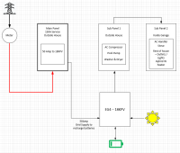
I have a 2 panel (typical layout) Main panel outside with a few heavy loads and a Sub panel in my garage. The easiest way would be to wire the grid feed out from the meter into the EG4 BUT I really don’t want to involve the utility company or have to pull permits.

After head scratching the past month the best, I can come up with is to remove the 240v loads from the main panel into a new SUB panel outside and then somehow daisy-chain or combine the 2 sub panels fed from the AC output of the EG4. (is there a specific combiner box / enclosure for performing this type of connection).

All thoughts welcome, thanks.

1687274037647.png
 
You would have to configure the EG4 for no export and move the sub panel to the AC out port of the EG4. My power company allows me to connect anything behind the meter without permission, as long as I am not exporting. A building permit would be required.
 
What you're describing is exactly the way I have the EG4 18KPV setup. I only use grid to charge the batteries or take over the load if there's no solar and the battery SOC is low.

Your diagram is basically the same as how it's hooked up in my case. The only difference is that my load from the 18KPV is going to a sub panel that is 100% run by the inverter. In your diagram there's no load from the inverter so I'm not sure where you intend on that going. The other thing to keep in mind is that the 18KPV is only rated for 50A output unless it's in grid bypass.

In the 18KPV you can disable "Grid Sell Back" and you can enable "Fast Zero Export" to ensure that the no power is sent back to the grid. See below:

1687979439964.png
 
What you're describing is exactly the way I have the EG4 18KPV setup. I only use grid to charge the batteries or take over the load if there's no solar and the battery SOC is low.

Your diagram is basically the same as how it's hooked up in my case. The only difference is that my load from the 18KPV is going to a sub panel that is 100% run by the inverter. In your diagram there's no load from the inverter so I'm not sure where you intend on that going. The other thing to keep in mind is that the 18KPV is only rated for 50A output unless it's in grid bypass.

In the 18KPV you can disable "Grid Sell Back" and you can enable "Fast Zero Export" to ensure that the no power is sent back to the grid. See below:

View attachment 154816
That’s some great information, thanks for sharing! Your correct about the drawing. I'll do another one as I was making assumptions on the 1st, It was just showing how my grid AC was today (as is). I 'm thinking ill move to 2 subs and keep my original as the main just suppling the battery backup for charging.

Can the AC input to the 18KPV be limited or throttled. I know it can take up to 200amp MAX but if I just use a 50amp breaker from my main panel supplying grid this can be managed - correct ?
 
Can the AC input to the 18KPV be limited or throttled. I know it can take up to 200amp MAX but if I just use a 50amp breaker from my main panel supplying grid this can be managed - correct ?

No it can't and at first I had the same concern before I actually thought about it more. If you size everything correctly then you shouldn't have an issue. The setting you can control is the grid to battery charge rate to make sure that you don't pull too much power during an AC charge. Since the output of the inverter is 50A, you shouldn't be sizing it for more than that, meaning that if it's on grid it still shouldn't be exceeding the 50A unless you are attempting to supply close to 50A of load + battery charging both from grid. I ran 60A to the inverter just to make sure I could account for this if it ever happened. If for some reason the load is higher your breaker will trip and do its job and then you'll have to re-think about the loads on the inverter.
 
similar to my system design with the XW Pro

refer to my schematic picture in post 1 of my thread

or below

thompson-ac-phase-240v-jpg.152951


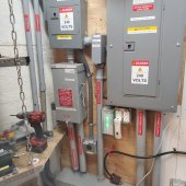
here is a picture of my AC side down stream from original service panel. Basically added a MTS and a Critical Loads Panel down from that

20230620_210717.jpg
 
@dougbert WOW thank you for sharing your build, i've been looking at that flow for the past 20mins and went down the rabbit hole of your build thread. Some real inspiration of what can be done, will come back to it for reference
 
After deliberating this is what I came up with which is more in line with what your suggesting.

As I drew this, I also thought what’s stopping me taking the full 150amp grid service to the 18KPV Using the sub panel lugs in my main panel compared to adding a smaller 50 or 70amp breaker? There will be no other loads in the main panel

I think the peak house consumption is around 9000watts with all the below running + surges for stop/start on top obviously.

1688068980621.png
 
In software construction adding a "new level of indirection" provides the ability to insert new functionally between two components.

Adding the transfer switch, additional grid panel and the new Critical Loads Panel downstream from the original main grid panel provides similar abilities to power wiring, like for adding a new generator or solar power source

BTW I have gone through several iterations on the AC side to get to this point. 23 years after my first system. Very few others did much back then and no web forums to share or learn from

have fun
 
Last edited:
After deliberating this is what I came up with which is more in line with what your suggesting.

As I drew this, I also thought what’s stopping me taking the full 150amp grid service to the 18KPV Using the sub panel lugs in my main panel compared to adding a smaller 50 or 70amp breaker? There will be no other loads in the main panel

I think the peak house consumption is around 9000watts with all the below running + surges for stop/start on top obviously.

View attachment 155002

planing now and putting in the infrastructure now for future features saves having to do REDOs

at the tail end of my thread I am documenting the new feed lines from grid to the transfer switch and inverter. I first put in 6 awg wire. Worked great 20 years ago, but now as I am planing for a 2nd XW Pro, I needed to replace those 6 gauge wires (and 1" conduit) with #2 wire and 1-1/4" conduit - ouch

Plan for a 2nd EG18k, even if you never do it.
 
Can the AC input to the 18KPV be limited or throttled. I know it can take up to 200amp MAX but if I just use a 50amp breaker from my main panel supplying grid this can be managed - correct ?
No it can't and at first I had the same concern before I actually thought about it more. If you size everything correctly then you shouldn't have an issue. The setting you can control is the grid to battery charge rate to make sure that you don't pull too much power during an AC charge.

Some grid-interactive battery inverters, which can blend power or backfeed the grid, can be programmed to limit current draw from grid. e.g. I can set 8A @ 120V max from grid and supply single, split-phase, or 3-phase up to 50A per phase with my Sunny Island.

For non-interactive inverters, you could install a stand-alone battery charger (e.g. Chargeverter) and run your system as an on-line UPS with programmable current draw.
 
Some grid-interactive battery inverters, which can blend power or backfeed the grid, can be programmed to limit current draw from grid. e.g. I can set 8A @ 120V max from grid and supply single, split-phase, or 3-phase up to 50A per phase with my Sunny Island.
Correct. For example the EG4 6500ex can limit the draw from grid. The EG4 18KPV however cannot, which is what he was specifically asking about.
 
ChargeVerter then, assuming it is programmable. $400.

 
ChargeVerter then, assuming it is programmable. $400.

I think there's some miscommunication here. The OP was asking if you could limit AC draw from the grid with the 18KPV, which you cannot. In other words you cannot say that in grid bypass the max amperage is 50A when the unit is capable of 200A in bypass. You can however limit the battery charge rate from the grid, which is what I said in post #5. I don't know what good this Chargeverter would do for the OP in this case.
 
What the Chargeverter would do is turn his system into an on-line UPS.
1) Current is drawn from grid, sufficient to charge battery and supply loads, or a set limit, whichever is less.
2) Current is drawn from battery by 18KPV to make up the shortfall in supplying loads.

This would limit bypass amperage to about 20A (per Chargeverter). Not really bypass, rather double-conversion.
Other people have opted for a second inverter, using it only as a battery charger.

What I would consider, but haven't tried, is feeding grid (or generator) transformer isolated and rectified into PV inputs of an inverter, as another way to feed in limited amount of power. I use Sunny Island, so I would do that with an old Sunny Boy. With frequency-watts, it would adjust power delivered to match load. May or may not work with PV inputs of a hybrid, but I'd rather not risk it. Plenty of old GT PV inverters available, at least for use with the hybrids that support AC coupling.
 
Back
Top