diy solar

diy solar

how to modify a car alternator for 48v charging

Think the 3 phases of alternator windings, presently wired Delta, could instead be wired zig-zag to produce single phase at double voltage?
I have been thinking a bit more about that idea.
If the three star windings were connected in series, in zig zag configuration, that should indeed generate twice the ac voltage, but it would only produce a single phase sinusoid across the final two wires. If that was rectified there would be a large ripple component and the average dc would be lower than the ac peaks.

Doing it my way with three bridge rectifiers, its very messy and inefficient, because of the voltage drop produced by always having six conducting diodes in series. But that does become less of a disadvantage at higher voltage.
It does produce nice classic six pulse overlapping rectification, and exactly double the dc output voltage, and with very low ripple content.

This is not just a thought experiment, I have actually built and tested this idea, and it definitely works.

I just used cheap and nasty thirty amp silicon bridges that I already had for convenience, but shottky diodes would be a much more elegant and efficient solution.
 
Last edited:
Yes, your rectification of each phase individually before summing is clever, and reduces ripple. My zig-zag idea just adds vectors to make a single phase, which crosses zero. Yours, always some positive voltage.

The main weakness of most alternators, I think, is poor heatsinking of positive diodes. They just have a small plate instead of the entire case. External fixes that.
 
It should not be too difficult to find a used low cost 24v alternator, and bring out connections from the three separate windings.
That should be ideal as a second alternator for a 48v battery in a camper.
The alternator could then be run at "normal" rpm without requiring an impractically small alternator pulley to reach 48v.
It also solves the problem of possibly over speeding the alternator during normal driving.
 
Last edited:
I once disconnected the three separate star windings, connected each winding to its own bridge rectifier, then connceted the dc side of the three rectifiers in series. That gave me exactly double the original dc voltage of the original, and with very low ripple voltage too!

If that was done with a 24v alternator it would be perfect for a 48v battery.
Thanks for reminding me.
That's quite a doable project for DIY.
 

Here is his build video, he has a few more on the task of improving the vibrations and increasing output.
 
I never proceeded to the next logical step of developing or adapting a suitable voltage regulator for this.
If luck holds, we might even be able to use the original 24v regulator that came in the alternator.

Assuming sixteen Lithium cells, and a final charging voltage of probably about 56 volts, each of the three bridge rectifiers will theoretically be putting out an average output of around 18.67v (neglecting diode drops).
The lowest of the three rectifiers that has its negative side grounded, will have a full wave rectified half sinusoid on the positive side of the bridge rectifier, with respect to ground, peaking up to roughly an expected 29.2 volts with an 18.67 average.

That could provide bulk dc power to supply the necessary power of just a few amps to the 24v alternator field winding, which would not be unreasonable for a 24v alternator. The stock original alternator usually has three smaller diodes to provide dc field power.

It then remains to supply a battery reference voltage to the existing electronics in the original 24v voltage regulator, which is very likely set to charge a 24v lead acid battery to probably about 28v. A 2:1 voltage divider of two equal value resistors may be all that is required to drop 56v down to 28v.
These will need to be fairly high resistance value as they will be constantly draining the battery when the alternator is not running.
It may be possible to do something clever with a small relay to solve that problem.

These voltage regulator modifications are all just completely untried ideas, and have not been tested so approach this with that in mind.
I am sure some of you guys can build on this, and come up with some neat and practical solutions.
 
I bet you could scrounge something used from a truck graveyard for two or three hundred bux.

For starters, how about doing the dirty deed to a 12v junk car alternator, to get 24v dc, just as a fun experimental learning project.
Could probably be done for just about nothing.

Something driven at constant repeatable speed (at lest 2,000 alternator rpm) will allow voltages and waveforms to be measured and compared, and the voltage doubling effect at the same rpm proven. It would also make a good test bed for some voltage regulator experiments.
The picture below shamelessly stolen from the internet.
 

Attachments

  • Daves-alternator-and-the-motor-used-to-drive-it.png
    Daves-alternator-and-the-motor-used-to-drive-it.png
    159.6 KB · Views: 5
Last edited:
I never proceeded to the next logical step of developing or adapting a suitable voltage regulator for this.
If luck holds, we might even be able to use the original 24v regulator that came in the alternator.

Maybe, regulating one of the windings. And exciting rotor with single-phase not rectified 3-phase.

By the way, what did you do with the "triode", 3 diodes that power alternator dash light and wake up alternator?

Assuming sixteen Lithium cells, and a final charging voltage of probably about 56 volts, each of the three bridge rectifiers will theoretically be putting out an average output of around 18.67v (neglecting diode drops).

No, I think they'll each be putting out around 28V. But with 60/120 degree angles not 0/180 degree, they add as vectors not linearly.

The lowest of the three rectifiers that has its negative side grounded, will have a full wave rectified half sinusoid on the positive side of the bridge rectifier, with respect to ground, peaking up to roughly an expected 29.2 volts with an 18.67 average.

Unless you mean RMS and peak, something close to these voltages, to deliver 56V peak from the three phases.

Of course, it waveform only hit 56A at peak, couldn't deliver any current at that voltage.
Are we talking about charging a battery directly with rectified AC?

These will need to be fairly high resistance value as they will be constantly draining the battery when the alternator is not running.
It may be possible to do something clever with a small relay to solve that problem.

But low resistance to provide current for rotor winding.
 
Maybe, regulating one of the windings. And exciting rotor with single-phase not rectified 3-phase.

By the way, what did you do with the "triode", 3 diodes that power alternator dash light and wake up alternator?
Output from one winding only will be a single phase sinusoid, full wave rectified, frequency might be 200Hz to 2Khz, not really sure.
Anyhow the field winding is highly inductive, so field current is very likely to be pretty strong dc with "some" ripple.
It should work fine regulating all three phases, even though power for the field winding now only comes from one phase.
Should be an interesting thing to look at. If field ripple is excessive, a catch diode across the field winding should fix it.

Never did anything with the three small diodes that normally supply the current to the field winding. Power to the field can come from the lower diode full wave bridge, as mentioned in the previous paragraph.
No, I think they'll each be putting out around 28V. But with 60/120 degree angles not 0/180 degree, they add as vectors not linearly.
Output of the three bridge rectifiers connected in series will add together to produce a pretty constant 56v with very low final ripple voltage.
Individual phases will each be going from zero to the peak voltage of one phase which will be a lot higher, but the sum of all three at any instant will still be a constant 56v.
The AVERAGE (not rms) of each must therefore be a third of 56v. Diode drops complicate the whole thing, so ignore that, its not really significant.

Unless you mean RMS and peak, something close to these voltages, to deliver 56V peak from the three phases.

Of course, it waveform only hit 56A at peak, couldn't deliver any current at that voltage.
Are we talking about charging a battery directly with rectified AC?

Only discussing voltages here under no load conditions.
As soon as its loaded up the 56v may be pulled down, and the voltage regulator will crank up the field excitation and try to maintain 56v.

Same with a standard car alternator, the voltage regulator tries to maintain perhaps about 14.2v. In this case it will be 56v.

But low resistance to provide current for rotor winding.

Power for the (rotor) field winding usually comes from three small extra diodes which only need to carry a very few amps, not the six much larger rectifier diodes. The startup energisation that usually comes from the dashboard alternator light can be replaced with a resistor supplying minimal current from the battery. A minor detail. Often there is enough residual magnetism to self start anyway, but its not always reliable.
It does not take very much. A dasboard light might be only 50mA.

Some alternators use this field energisation point as the battery voltage reference, and some alternators run a seperate sensing wire right back to the battery positive battery terminal. That is done to sense the voltage right at the battery, not at the alternator, to eliminate errors due to voltage drop in the alternator to battery connection. With luck our 24v alternator may be one of those with the extra sensing wire.
It might be a feature to look for when purchasing a 24v alternator.
 
Last edited:
Output from one winding only will be a single phase sinusoid, full wave rectified, frequency might be 200Hz to 2Khz, not really sure.
Anyhow the field winding is highly inductive, so field current is very likely to be pretty strong dc with "some" ripple.

Could be true for rotor exciter winding. If current does not drop to zero when sine wave from single stator winding drops to zero, that means your full-wave rectifier acts as freewheeling diode. For original 3-phase configuration, the diodes don't provide freewheeling, rather direct current through windings, one of which is trying to push current in same polarity. If inductance of rotor is strong enough it could push current up faster.

Stator coil I think has inductance is much lower. fewer turns of thicker wire.

As for inductance, any transformer or rotating machinery actually has quite small energy stored in that inductance. It is whatever no-load current and the (reduced) inductance it may have at that current. (transformers I've tested operate significantly into saturation on BH curve, carrying 10x or more the current they would at the inductance measured with low current.)

I would think use of alternator would try to decrease current in rotor. Would need to measure voltage/current of exciter vs. load on alternator output.

Fun fact - funny things happen to magnetic field in alternator based on current output. My Honda CB77 had permanent-magnet 3-phase alternator, switchable for how many windings go to DC system depending on whether lights were on. Equalization (electrolysis) in FLA battery was the voltage regulator. You can guess who loses that tug of war. I tried to make a voltage regulator by switching battery connection with transistors. It erased the permanent magnets.

Should be only hundreds of Hz. Engine RPM and pully diameters would tell you. 3600 RPM is 60 Hz.
Power diodes are so slow that about 1 kHz is the limit, beyond that they continue conducting too long in the reverse direction (per my education, haven't tested.) So 400 Hz systems are OK.
I thought this was true for all silicon junction diodes, and Schottky was needed for high frequency, but here are silicon diodes with some nanoseconds reverse recovery time good for SMPS.


It should work fine regulating all three phases, even though power for the field winding now only comes from one phase.
Should be an interesting thing to look at. If field ripple is excessive, a catch diode across the field winding should fix it.

Never did anything with the three small diodes that normally supply the current to the field winding. Power to the field can come from the lower diode full wave bridge, as mentioned in the previous paragraph.

Alternator has 3 positive power diodes, 3 negative power diodes, 3 small positive diodes in the "triode" for exciter winding.
That uses the 3 negative diodes to complete circuit, so if you rearrange windings, they live at different voltage and that circuit wouldn't work.

I think you could transformer-isolate the three windings with secondaries reassembled as delta to feed a 3-phase rectifier for exciter.
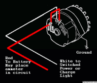
If dash board idiot light is needed to wake it up you'd want to feed that a suitable voltage (1/2 of total should get light functioning and avoid backfeeding light)


Output of the three bridge rectifiers connected in series will add together to produce a pretty constant 56v with very low final ripple voltage.

Because as you note it has the ripple of 6 phase not 3 phase, due to individual bridge rectifiers.

Individual phases will each be going from zero to the peak voltage of one phase which will be a lot higher, but the sum of all three at any instant will still be a constant 56v.

The AVERAGE (not rms) of each must therefore be a third of 56v. Diode drops complicate the whole thing, so ignore that, its not really significant.

I disagree. The vector sum must be 56V (the three windings are not in phase). Each will be half of 56V, 28V. When one is pointed straight up, the other two zigzag out and back 28V at 60 degree angle, making 28V in phase with the first. The two form an equilateral triangle open on one leg.

Power for the (rotor) field winding usually comes from three small extra diodes which only need to carry a very few amps, not the six much larger rectifier diodes. The startup energisation that usually comes from the dashboard alternator light can be replaced with a resistor supplying minimal current from the battery. A minor detail. Often there is enough residual magnetism to self start anyway, but its not always reliable.

It does not take very much.

Right - it isn't the 3 diodes powering the dashboard light, it is battery through ignition key powering dashboard. If that is higher than the 3 diodes, current flows through the light into the rotor's exciter winding.

I messed up a couple times when I had bad (shorted) windings in a "rebuilt" alternator I put in a Saab, tried jumpering some things and alternator tried to charge battery through the "triode", burning it out. After having it "rebuilt" multiple times, I told the shop I suspected windings. He watched with a scope while spinning and observed dropouts, shorting between windings. It was fine after getting rewound (not just replacing triode). I also had electrical failures due to corroded crimped grommet in fuse box. I finally went at that with a wire brush and soldered with strong flux, solving the cooling fan failures. But repeated overheating had caused head crack by then.

Residual magnetism - does alternator work if idiot light is removed or burned out?

Some alternators use this field energisation point as the battery voltage reference, and some alternators run a seperate sensing wire right back to the battery positive battery terminal. That is done to sense the voltage right at the battery, not at the alternator, to eliminate errors due to voltage drop in the alternator to battery connection. With luck our 24v alternator may be one of those with the extra sensing wire.
It might be a feature to look for when purchasing a 24v alternator.

Some of mine I think measure from the "triode". When one or two of the positive power diodes fails, battery no longer gets regulated to full charge. I realized they have less heatsink. All that would be required to make it robust would be temperature sensor on that heatsink cutting back output current. But I had this failure in K2500 with built-in regulator, closer to the heatsink so could have been designed that way but wasn't.

External rectifier with big heasink would be the way to add-on protection.
 
Frequency is actually quite high, even at only 2,000 rpm. Its a multi pole machine, so each turn generates several cycles, and full wave rectification doubles the ripple frequency beyond that. The rotor has a lot of turns of thin wire, usually about four amps will drive the steel rotor up to near saturation, even with the air gap. Its the reason why such a physically small alternator can put out so much power.
Vastly more than a 50/60Hz machine of similar size.

Yes you are quite right, when one phase goes through zero, the other two at that instant add together to create 56v. But all three waveforms are constantly varying.
If you average the voltage across one phase (0.637 x peak) over several cycles it must be one third of 56v.
The current in a series connected choke is also the average of the ac voltage, not the rms.

A multimeter measures rms not average which is eleven percent higher. Anyhow, we are really splitting hairs here.
Pretty sure taking all factors into account, using the full wave rectified output of only one winding should come pretty close to being able to fully energise the field winding using the original voltage regulator. As I said earlier, I never attempted to get a voltage regulator working.
I was only curious about the voltage doubling effect of using three bridge rectifiers connected in series, and that worked perfectly.

It might even have an application for a wind turbine ???

Residual magnetism - does alternator work if idiot light is removed or burned out?

Yes sometimes. If you spin it fast enough it can suddenly and quite violently start up. There may only be enough residual magnetism to put a very few milliamps into the output windings, which goes straight back into the field winding via the regulator. That strengthens the residual magnetism.
Its a quite strong positive feedback effect, which can be pretty instantaneous once there is sufficient rpm (a lot) to get the process started.
It only takes a small current from the dash alternator lamp to provide enough current for more predictable and gentle start up. After that its self sustaining.

Some of mine I think measure from the "triode".

Yes, that is quite common. The bulk dc power for the field always comes from the "triode" but some alternators bring out the voltage sensing connection to an additional pin on a plug located on the back of the alternator. There are quite a few different variations of this, but the diagram below has the usual charging light on the white wire pin 2.
Pin 1 is the voltage reference pin which can be linked to the alternator dc output, or go right to the battery positive terminal.
 

Attachments

  • 3 wire alternator.png
    3 wire alternator.png
    9.5 KB · Views: 3
Last edited:
Back
Top