diy solar

diy solar

I am a beginner who is wanting to build their first solar setup. I would like some feedback after drawing a schematic.

ThatCoolNerd

New Member
Joined
Apr 27, 2024
Messages
11
Location
United States of America 🇺🇸
I am planning on building a small (~1.2kwh) mobile system that can be hauled around the home and yard for various AC applications. I do not have any needs for 12V DC output at the moment.

I would like some feedback regarding this diagram, as I'm a complete beginner. I have been reading and watching a lot of videos regarding solar, batteries, and electricity in general. I anticipate this little project will cost about $950-$1050 after shipping, tax, and purchasing of the tools (large/small wire crimpers/strippers), and materials.

I am not married to the idea of purchasing the EPEVER Tracer 2210AN as my charge controller. I was originally planning on going with a Victron BlueSolar MPPT 100/20, but the terminals are small and I've heard many beginners accidentally break them because of the flimsy terminals. If you have a suggestion for a better charge controller with proper terminals for my use-case, I'd love to hear!

I'm just trying to be more responsible and not only be more self-sufficient, but also learn a new skill.

Most importantly, does this look safe? Thank you all for reading!

P.S. Sorry the image is so big. It's my first schematic.
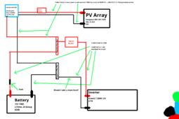

solarchargetest.png
 
Skip the EPEver, they have a known issue with not tracking the PV voltage. Go with HQST, Rich Solar, or even PowMr for a decent MPPT controller. Also, the price difference between a 20-ish amp and a 40-ish amp is negligible, but having a higher PV Voltage will save you trouble later. It also lets you put more PV into the system when you realize 100w isn't that much.

Your wire and breaker sizes look good. (y)
 
You do not need overcurrent protection (OCP, a breaker or fuse) between panel and MPPT - only when you have more than two strings in parallel.

OCP is for wires, not equipment.

OCP should be 1.25X wire rating (rounded up to nearest size)

OCP is always on (+).

You need OCP between MPPT and bus bar to protect 8awg MPPT wire. Given that the max output of the EPEVER is 20A, you will never have more than 20A on that wire unless you upgrade MPPT.

You need to factor in 85% DC-AC efficiency, so calculated inverter load will be 117A, x1.25 = 146A, round up to 150 (consult inverter manual for their recommendations).

Fuses/breakers must have adequate AIC rating, i.e., if the current is too large, it can arc across the fuse/breaker, it will never interrupt current. LFP OCP typically needs 10,000-20,000 AIC.

And just to piss @Rednecktek off, go for Victron MPPT instead. With their price reduction, they're not much more than Chinesium MPPT. :p
 
OCP should be 1.25X wire rating (rounded up to nearest size)

You need to factor in 85% DC-AC efficiency, so calculated inverter load will be 117A, x1.25 = 146A, round up to 150 (consult inverter manual for their recommendations).
1.25x wire rating, not max load? Just making sure.

I'm assuming I'll need an appropriately upsized cable (0 AWG) as well to accommodate the efficiency?

Thank you for the information!
 
I am partial to a MRBF fuse on the battery post (125amps + holder - get them from Mouser electronics cheaper than amazon). Class T between bus bar and inverter.

And piss off @Rednecktek and you won't be sorry, get the Victron.

And to piss off @sunshine_eggo I am going to mention that the Li Time 60amp MPT is way less than a 60 amp smurf unit and is well built. Get the new design verse the one that looks like a PowMr clone.

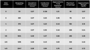
Wire - windy nation chart - 105c pure copper welding wire, you can use 2 awg

1714841543947.png
 
1.25x wire rating, not max load? Just making sure.

You can technically chose a lower fuse if you'd like, but if you don't have at least 1.25X the max current, you risk triggering "nuisance" tripping of the OCP

I'm assuming I'll need an appropriately upsized cable (0 AWG) as well to accommodate the efficiency?

Differernt specifications of battery wire have different ratings.


Suitably rated 4awg could handle 160A.

NEC awg specifications for 75°C cable is 150A @ 0awg
 
I am partial to a MRBF fuse on the battery post (125amps + holder - get them from Mouser electronics cheaper than amazon). Class T between bus bar and inverter.

And piss off @Rednecktek and you won't be sorry, get the Victron.

And to piss off @sunshine_eggo I am going to mention that the Li Time 60amp MPT is way less than a 60 amp smurf unit and is well built. Get the new design verse the one that looks like a PowMr clone.

Bruh... I'd happily sacrifice 10A and gain BT function for an extra $30.

But... I piss blue... :p
 
A few errors. 1- 100 w panel does not output 20a. It is closer to 5-6a. You do not need 8awg wire even if you add another panel. 2 -100w panels will still be below the 20-25a capacity of 12awg. Skip the Epever and go for a HQST or Sky Blue.
 
Whichever flavor you get be it smurf blue or another color - make sure it is the right output voltage for your battery. Some do all 4 common voltages and others not so much. The cheapest stuff seems to be for 48v but then you will spend more on a battery and be less portable.

And when you buy tool to crimp and cut, resist the urge to cheap out if you can. Temco is a great brand for crimpers but spendy. The cheap brands on amazon typically mark their mm based dies as awg and are a hair off.

If you want to save the bucks until you are ready to do more buy the premade cables Eggo linked to
 
Last edited:
A few errors. 1- 100 w panel does not output 20a. It is closer to 5-6a. You do not need 8awg wire even if you add another panel. 2 -100w panels will still be below the 20-25a capacity of 12awg. Skip the Epever and go for a HQST or Sky Blue.
100w/12v * 1.2 = 10a
2 of them = 20a

I know in realistic conditions panels will not pull their maximum rate the majority of the time, but don't you need to spec your system to theoretical maximums to be safe?

Whichever flavor you get be it smurf blue or another color - make sure it is the right output voltage for your battery. Some do all 4 common voltages and others not so much. The cheapest stuff seems to be for 48v but then you will spend more on a battery and be less portable.

And when you buy tool to crimp and cut, resist the urge to cheap out if you can. Temco is a great brand for crimpers but spendy. The cheap brands on amazon typically mark their mm based dies as awg and are a hair off.

If you want to save the bucks until you are ready to do more buy the premade cables Eggo linked to
I'm really just trying to find the smallest, reliable controller possible (with a little extra headroom for another 100w panel) with battery terminals that don't suck.

I was planning on splurging and getting Klein crimpers/wire strippers and a Temco hammer crimper for the larger AWG cables.
and you won't be sorry, get the Victron.

And to piss off @sunshine_eggo I am going to mention that the Li Time 60amp MPT is way less than a 60 amp smurf unit and is well built. Get the new design verse the one that looks like a PowMr clone.

Wire - windy nation chart - 105c pure copper welding wire, you can use 2 awg

View attachment 213322
I've been using this website as a reference for AWG under "Maximum amps for power transmission"

Does this seem off? I notice the numbers in your chart are quite different.


Thank you all for the help, you have no idea how much this means. I don't have any electricians in my family haha.
 
100w/12v * 1.2 = 10a
2 of them = 20a

I know in realistic conditions panels will not pull their maximum rate the majority of the time, but don't you need to spec your system to theoretical maximums to be safe?


I'm really just trying to find the smallest, reliable controller possible (with a little extra headroom for another 100w panel) with battery terminals that don't suck.

I was planning on splurging and getting Klein crimpers/wire strippers and a Temco hammer crimper for the larger AWG cables.

I've been using this website as a reference for AWG under "Maximum amps for power transmission"

Does this seem off? I notice the numbers in your chart are quite different.


Thank you all for the help, you have no idea how much this means. I don't have any electricians in my family haha.
Hammer crimper isn't great for the long run. If used in a full install it wouldn't meet NEC because it doesn't imprint wire size into the lug. For little stuff or one off use it is fine. The deal with a hammer crimper is you need to put it on concrete like a garage floor or on a anvil, then use a 2.5~3lb sledge and hit it *hard* a couple of times. You will get the hang of it after a few times. When you do it the sound will change when you have it right. First is a ringing sound, then when it is hit enough it sounds like a dull thud. With a regular hammer it is hard to get it done. Some use a bench vise and a cheater bar to squeeze it gradually.

When dealing with panels and batteries - voltage adds when in series and current adds when in parallel.

So when you string 4 batteries in series together than can only charge at 10amps each, the whole string is limited to 10 amps.

When you put panels together in parallel the Isc rating adds and the Vmp stays the same. If you string them in series the Vmp adds and the Isc stays the same.

An unpopular choice if cost is more important than efficieny would be to use a PWM controller verse a MPPT. A PWM at 30amps is about $35 for a good one. It is a LOT less efficient but it works. The downside is that some energy from the solar panels goes unused because of how it works. With a MPPT all the energy the battery can take is used.

The downside of the PWM is your panels would be limited to the voltage of your battery. i.e. a 12v panel that puts out 18ish volts is all you could use. With a MPPT you can string more or higher voltage together and it will use all the energy produced up to the MPPT max or the battery max.

The wire chart differences are because of the cable type and heat rating. The chart you are using is for standard cable with a 75c or 90c sheath like THHN or romex. The chart I posted is for welding wire with a 105c rating on the sheath. Welding wire has a much higher strand count and bends easier.

With wire it all comes down to cross section area * ampacity of the copper and the sheath makup. There is solid copper like what is in the walls of your house. Stranded copper for things that need to vibrate and bend. Battery wire that has a higher strand count and can vibrate and bend more and has a higher temperature rating. And, welding wire which has an even higher strand count and a more rubbery sheath. There are probably a dozen or so more types but those are most common.

Make sure you get pure copper wire verse CCA (copper clad aluminum). The CCA has to be at least a full awg bigger or more than copper for the same current.
 
Last edited:
100w/12v * 1.2 = 10a
2 of them = 20a

...
The panels output higher voltage than 12vDC your SCC reduces it to battery voltage. I have arrays of over 2000w running on 10awg that almost never exceed 10a. to the SCC.

Most 100w panels Vmp is 18 volt DC. Thus 5-6a.

BTW as Robbob mentioned if you wire in series you still would have only 5-6a coming from the panels.
 
I am so stupid. I had the biggest brainfart. In all of my trying to figure out wire and circuit breaker sizes, I'd forgotten series compounds the voltage and parallel is the opposite.

Nothing about any of this is particularly difficult, it seems, however there's just a lot to keep track of and verify before the purchasing and subsequent building of components. Thanks all again for the help.
Hammer crimper isn't great for the long run. If used in a full install it wouldn't meet NEC because it doesn't imprint wire size into the lug. For little stuff or one off use it is fine. The deal with a hammer crimper is you need to put it on concrete like a garage floor or on a anvil, then use a 2.5~3lb sledge and hit it *hard* a couple of times. You will get the hang of it after a few times. When you do it the sound will change when you have it right. First is a ringing sound, then when it is hit enough it sounds like a dull thud. With a regular hammer it is hard to get it done. Some use a bench vise and a cheater bar to squeeze it gradually.

When dealing with panels and batteries - voltage adds when in series and current adds when in parallel.

So when you string 4 batteries in series together than can only charge at 10amps each, the whole string is limited to 10 amps.

When you put panels together in parallel the Isc rating adds and the Vmp stays the same. If you string them in series the Vmp adds and the Isc stays the same.

An unpopular choice if cost is more important than efficieny would be to use a PWM controller verse a MPPT. A PWM at 30amps is about $35 for a good one. It is a LOT less efficient but it works. The downside is that some energy from the solar panels goes unused because of how it works. With a MPPT all the energy the battery can take is used.

The downside of the PWM is your panels would be limited to the voltage of your battery. i.e. a 12v panel that puts out 18ish volts is all you could use. With a MPPT you can string more or higher voltage together and it will use all the energy produced up to the MPPT max or the battery max.

The wire chart differences are because of the cable type and heat rating. The chart you are using is for standard cable with a 75c or 90c sheath like THHN or romex. The chart I posted is for welding wire with a 105c rating on the sheath. Welding wire has a much higher strand count and bends easier.

With wire it all comes down to cross section area * ampacity of the copper and the sheath makup. There is solid copper like what is in the walls of your house. Stranded copper for things that need to vibrate and bend. Battery wire that has a higher strand count and can vibrate and bend more and has a higher temperature rating. And, welding wire which has an even higher strand count and a more rubbery sheath. There are probably a dozen or so more types but those are most common.

Make sure you get pure copper wire verse CCA (copper clad aluminum). The CCA has to be at least a full awg bigger or more than copper for the same current.
What tools would you recommend for larger AWG cable? I'm a "buy once, cry once" kind of a guy. I'm gonna get Klein for the 10AWG or smaller wire.

Cost really isn't an issue. I just don't want to shell out money for an SCC into which I can't fit my cables, or have terminals break. I think I'm going to look into the HQST 20A MPPT controller someone mentioned. Initial research shows reviews seem favorable.

I'm not going to use CCA, but ty for the heads-up. I'm just going to use copper for simplicity.
 

The meter on this is great, I wish I had bought a different clamp meter that would capture inrush current. But at the time that wasn't my focus. But after working in a calibration lab in the Navy I will never buy anything but Fluke DMM .

OH and these - these specialty meters to get in Fluke they either aren't made or cost a grand.
measure miliohms and internal battery resistance

On my list, not currently in hand
Megger meter for testing insulation
solar panel meter
Clamp meter with inrush

These are my go-to tools for most of this, I have others that are 30+ years old some mine and some inherited from Pop. He was a machinest all his adult life so I have some interesting tools from when his shop closed and he passed.
 
Last edited:
And I do subscribe to buy it once and keep it forever philosophy when it comes to tools and meters.
 
I am planning on building a small (~1.2kwh) mobile system that can be hauled around the home and yard for various AC applications. I do not have any needs for 12V DC output at the moment.

I would like some feedback regarding this diagram, as I'm a complete beginner. I have been reading and watching a lot of videos regarding solar, batteries, and electricity in general. I anticipate this little project will cost about $950-$1050 after shipping, tax, and purchasing of the tools (large/small wire crimpers/strippers), and materials.

I am not married to the idea of purchasing the EPEVER Tracer 2210AN as my charge controller. I was originally planning on going with a Victron BlueSolar MPPT 100/20, but the terminals are small and I've heard many beginners accidentally break them because of the flimsy terminals. If you have a suggestion for a better charge controller with proper terminals for my use-case, I'd love to hear!

I'm just trying to be more responsible and not only be more self-sufficient, but also learn a new skill.

Most importantly, does this look safe? Thank you all for reading!

P.S. Sorry the image is so big. It's my first schematic.


View attachment 213312
Do you have an update schematic with the updates you made? I'm starting on almost identical, except mine will be 24V.
 

The meter on this is great, I wish I had bought a different clamp meter that would capture inrush current. But at the time that wasn't my focus. But after working in a calibration lab in the Navy I will never buy anything but Fluke DMM .

OH and these - these specialty meters to get in Fluke they either aren't made or cost a grand.
measure miliohms and internal battery resistance

On my list, not currently in hand
Megger meter for testing insulation
solar panel meter
Clamp meter with inrush

These are my go-to tools for most of this, I have others that are 30+ years old some mine and some inherited from Pop. He was a machinest all his adult life so I have some interesting tools from when his shop closed and he passed.


Got a new meter -

The earlier clamp meter I had listed didn't do DC current or inrush current. The new one does both.

The fluke version with the same features was $900
 
Back
Top