Input impedance is related with the impedance of the ADC, not the shunt.A 100 mV 100 A shunt is 1 mOhm... How do you call that if not very low?
You are using an out of date browser. It may not display this or other websites correctly.
You should upgrade or use an alternative browser.
You should upgrade or use an alternative browser.
I want to make my own BMS
- Thread starter Pidjey
- Start date
That is why I said not very high input impedance is needed.Yes but since the shunt impedance is very low you can have a low input impedance amplifier.
Looks like I am inventing electronics again when these conceps have more than half a century. This example is for allowing charging only. For discharging only just swap the behaviour of the Mosfets.Yes, please, because I really don't see how you can avoid this problem.
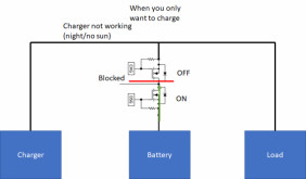
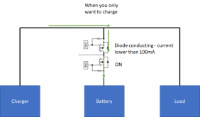
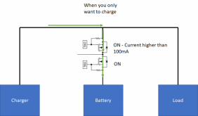
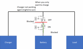
Last edited:
Ok, schematic #2, there's a body diode conducting.
You were saying the opposite:
While we were trying to tell you that you can't avoid having the current going through the body diode.
You were saying the opposite:
This device has diode emulation to allow only charge or discharge. This means body diode is not even used. Whout controlling FETs independently diode emulation cannot be performed.
As soon as current changes and body diode starts conducting, mosfet goes on to avoid conducting through the body diode. If current goes reverse, it blocks again. This is done in buck converters at hundreds kHz speed.
While we were trying to tell you that you can't avoid having the current going through the body diode.
Yes, less than 100mA until the right polarity is detected. Is that a problem?Ok, schematic #2, there's a body diode conducting.
You were saying the opposite:
While we were trying to tell you that you can't avoid having the current going through the body diode.
Again and again and again. As it is written, it only conducts very low currents when the right polarity is detected, as soon as current in the right polarity is detected it goes on and it can conduct hunders of amps in on state without diode drop. If reverse current is detected it goes off.
It is just the concept of diode emulation, I have not invented it.
Last edited:
Why would it be less than 100 mA? the charger will provide all the current it can...
And in the other direction? because you can't just tell the loads to limit their draw to 100 mA... (which would be useless for 99 % installations anyway given it's only a few W).
And in the other direction? because you can't just tell the loads to limit their draw to 100 mA... (which would be useless for 99 % installations anyway given it's only a few W).
Because as soon as current starts ramping up conducting through the body diode and it is detected, the mosfet goes on to avoid current conducted through the body diode. 100mA is just orientative to say as a threshold current. If current goes down and starts being reverse, the mosfet goes off blocking.Why would it be less than 100 mA? the charger will provide all the current it can...
And in the other direction? because you can't just tell the loads to limit their draw to 100 mA... (which would be useless for 99 % installations anyway given it's only a few W).
Again, please just check what is diode emulation
This is from the datasheet. It does not call it diode emulation but it is how this concept is called:
If the CHG FET is off, the DSG or PDSG FET is on, and a discharge current greater in magnitude than a programmable threshold (that is, a significant discharging current) is detected, the device will turn on the CHG FET, to avoid current flowing through the CHG FET body diode and damaging the FET. When the current rises above the threshold (that is, less discharge current flowing), the CHG FET will be turned off again if the reasons for its turn-off are still present.
If the DSG FET is off, the CHG or PCHG FET is on, and a current in excess of a programmable threshold (that is, a significant charging current) is detected, the device will turn on the DSG FET, to avoid current flowing through the DSG FET body diode and damaging the FET. When the current falls below the threshold (that is, less charging current flowing), the DSG FET will be turned off again if the reasons for its turn-off are still present.
I see, you're using the shunt sensed current to control the MOSFETs. That wasn't explained on the schematic 
That's a good idea
Edit: although it relies on some software or extensive hardware to work, so it's not ideal either.
That's a good idea
Edit: although it relies on some software or extensive hardware to work, so it's not ideal either.
Factory400
Solar Enthusiast
- Joined
- Jul 15, 2020
- Messages
- 387
That is baked into the silicon......it is a fancy ideal diode controller.I see, you're using the shunt sensed current to control the MOSFETs. That wasn't explained on the schematic
That's a good idea
Probably could have been said that this is not part of @Pidjey circuit design - but rather a function/feature of a specific device and spelled out in the datasheet.
That is why I kindly asked you check about diode emulation as it is only possible measuring the current.
Glad to know that it is clear now
Glad to know that it is clear now
I never said that it was my design but in the case it would have been my design, it would not invalidate the concept of using emulated diode. It was not invented by me and provably not by TI (at least in the last 60 years)That is baked into the silicon......it is a fancy ideal diode controller.
Probably could have been said that this is not part of @Pidjey circuit design - but rather a function/feature of a specific device and spelled out in the datasheet.
That is baked into the silicon......it is a fancy ideal diode controller.
I've the feeling that internally those BMS chips aren't really a hardware solution but a MCU with fixed code... I can be wrong but that's the easiest solution (and by far...) so I don't see why they would do it a different way.
Probably could have been said that this is not part of @Pidjey circuit design - but rather a function/feature of a specific device and spelled out in the datasheet.
Yep, half of it was missing, MOSFETs alone can't do that...
Provably as its block diagram says there is a digital coreI've the feeling that internally those BMS chips aren't really a hardware solution but a MCU with fixed code... I can be wrong but that's the easiest solution (and by far...) so I don't see why they would do it a different way.
Yep, half of it was missing, MOSFETs alone can't do that...
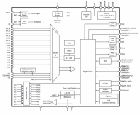
I could also have done it using an MCU and I2C commands or analog circuit (bi directional current amplifier+2 comparators with enable) as pins for overriding the mosfet state are exposed. My feeling was that you were saying that it was electrically not possible as I read from your previous posts. Done by the chip or externally does not invalidate the concept. I always said that mosfets were controlled on and off when current was detected to create diode emulation. If you know how the concept diode emulation works as I explained and asked to take a look, nothing is missing.
I think it is time to stop this discussion and move forward.
Last edited:
But please..... try to help me in the way I am asking. As I have always said, I am asking about which features are good to have, not how to implement them. That is my problem if it does not work. I do not want to say that I do not appreciate your technical recomendations because I do, but I am not looking/asking for them now. I am asking for the features I need in my system. There will be a moment later where I will start asking about these technical question but it is not the time now.
I asked, low charge current is needed when battery drops to 2.5V?
I would like to avoid bat+ and bat- in the same place. Would you put shunt away or mosfets away?
Please, let me do things wrong. I think shunt can be away from ADC from my experience doing remote measurements. Also as seen in BMV700 using a 10m cable from shunt to adc. As I have said, I have a degree, master, phd and years of experience in electronics, I do not want to say that I am right in every thing but I am not dumb.
If it does not work and I did not ask/listened to your recomendations, it is my problem, but please, help me moving forward writing my requieriments/features.
How I solve it electronically will come later.
Last edited:
Factory400
Solar Enthusiast
- Joined
- Jul 15, 2020
- Messages
- 387
I am definitely interested to learn if there is any problem with 'full rate' charging a cell from 2.5v. I do not know the answer, but very interested.
My current setup does not let any cell go below 2.9v or so and my charge setting on the Victron is on a low setting most of the time. At some point, I will need/want to fast charge from a 0% SOC battery.
My current setup does not let any cell go below 2.9v or so and my charge setting on the Victron is on a low setting most of the time. At some point, I will need/want to fast charge from a 0% SOC battery.
Thank you for your understanding. Me too. It is something I would like to learn. I do not know if it is important/useful.I am definitely interested to learn if there is any problem with 'full rate' charging a cell from 2.5v. I do not know the answer, but very interested.
My current setup does not let any cell go below 2.9v or so and my charge setting on the Victron is on a low setting most of the time. At some point, I will need/want to fast charge from a 0% SOC battery.
I am also not planning to set low cutoff voltage lower than 2.9V but circunstances can happen. One situation could be afer a capacity test. Another situation could be bypassing the 2.9V cut off manually in case of emergency.
If it is completly useless I will not implement it as it needs aditional circuitery.
Last edited:
DISCLAIMER: I do not know if this is true, it is something I would like to learn.
I have read some people talking about that chargers not designed for lithium can damage lithium batteries. This is because after completing the charge of the batteries they do not stop charging because they are in float charging phase. I do not know if this is true.
I am curious to test the function of allowing discharging and blocking charging to overcome this problem when battery is completly charged. Charging would be blocked until next charging cycle as lithium chargers do (as I have read).
(Again, how to do it, it is my problem)
Last edited:
I asked, low charge current is needed when battery drops to 2.5V?
That's a bit rude... And I answered: https://diysolarforum.com/threads/i-want-to-make-my-own-bms.17003/page-7#post-198795
I would like to avoid bat+ and bat- in the same place. Would you put shunt away or mosfets away?
Or you can put the MOSFETs on the negative side so you don't have both the high current positive and negative near each other.
Please, let me do things wrong.
Weird, but... ok.
If it does not work and I did not ask/listened to your recomendations, it is my problem, but please, help me moving forward writing my requieriments/features.
A list of the features you have currently would be helpful. Also, help in what way? Only you can know what you want in your BMS unless I missed something.
I do not know if it is important/useful.
Well, since you have a degree, a master and a phd, as you said, I guess you know how to use a search engine...
DISCLAIMER: I do not know if this is true, it is something I would like to learn.
I have read some people talking about that chargers not designed for lithium can damage lithium batteries. This is because after completing the charge of the batteries they do not stop charging because they are in float charging phase. I do not know if this is true.
I am curious to test the function of allowing discharging and blocking charging to overcome this problem when battery is completly charged. Charging would be blocked until next charging cycle as lithium chargers do (as I have read).
(Again, how to do it, it is my problem)
Hmm... before doing a BMS please read about lithium charging profile because that's like step 1 (and no, we'll not explain it in details here since it would take a lot of time and text, people already did it numerous times; again, google will answer all your questions about that).
Last edited:
I have been 2 hours explaining you what emulation diode works when you can find it in the first link in a google search. I even prepared diagrams. You could do the same right? If I am asking it is because there are dozens of posts with contradictory information even in this forum.Hmm... before doing a BMS please read about lithium charging profile because that's like step 1 (and no, we'll not explain it in details here since it would take a lot of time and text, people already did it numerous times; again, google will answer all your questions about that).
I am do not know what it is important for other people that can be useful for me and I have not realized, that is why I am asking. Maybe you missed that learning from other people can be helpful.A list of the features you have currently would be helpful. Also, help in what way? Only you can know what you want in your BMS unless I missed something.
I asked what is the recomended C-rate for low voltage batteries and I got no answer.A bit rude... And I answered: https://diysolarforum.com/threads/i-want-to-make-my-own-bms.17003/page-7#post-198795
I think you are the one being rude with me as I have been trying to explain everything and your only answers are, that does not work. As I want to move forward my project I am not going to follow lack of content answers.
Similar threads
- Replies
- 12
- Views
- 482
- Replies
- 1
- Views
- 212
- Replies
- 11
- Views
- 599
- Replies
- 14
- Views
- 477


