diy solar

diy solar

Iconica 3000 hybrid inverter neutral bonding

TerryBarnaby

New Member
Joined
Oct 12, 2022
Messages
8
Hi, I have recently purchased an Iconica 3000 24V MPPT "hybrid" inverter that I intend to use as a sort of UPS for some computer systems and/or to power some garden features with mainly Solar input, batteries and extra mains charging.
I tested it at work and it seems a reasonably sturdy piece of kit and appears to work fine although cheap. It seems like there are a few similar clones of this design around.
However I just tested it at home by powering its AC IN input from a 13 Amp socket at my house and it tripped an RCD immediately. On checking its terminals it has AC IN with earth, neutral and live and AC OUT with neutral and live. The earth terminal was connected to the case as expected but the earth was also internally connected to both the AC IN and AC OUT neutral lines.
We live in the countryside in the UK and have a TT mains system which has live and neutral from the grid and separate local earth rods. The neutral can be quite a few volts different to ground with the separate overhead wires and others sharing the transformer etc. so tripping the RCD when the inverters Earth is connected to the neutral would be expected depending on line condition when connected.
Is it expected that these types of UPS/off-grid inverters would have their AC IN and OUT neutral lines shorted to earth internally ?
 
I think that the 1st thing to connect are the batteries (DC) and probably wise to pre charge the inverter with a suitable resitor. The manual says
Please follow below steps to implement AC input/output connection:
1. Before making AC input/output connection, be sure to open DC protector or disconnector first.

I read that as the DC supply needs to be on and the AC connected to the inverter AC input while the AC is disconnected via breaker of suitable rating . Hopefully someone with experience of that inverter will chip in and advise as I haven't ever used one.
 
Thanks for the reply.
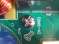
I have just found out today, from Photonic Universe who supplied the inverter, that these inverters have a screw inside shorting the Neutral to Earth by default. Not mentioned in the manuals or anything else I have seen, technical info is poor these days! Anyway easy to remove and now it is fine when supplied through an RCD. I really don't know why this was the default. I guess it comes from completely off-grid battery/solar only inverters where bonding the Neutral output to Earth is probably best. But with AC IN I personally don't think this is a good idea as default and it would be easy to link outside the unit if/when wanted and would be obvious this has been done.
Also note for anyone else using these units the AC OUT Neutral is directly connected to the AC IN Neutral and the bypass relay appears just to switch the Live line.
TNC-S earthing system is the most common standard in the UK, combined neutral and earth return to the local sub station, it sounds like you have a TNS arrangement with a separate earth electrode hence why your RCD trips with the combined system of CPE to Neutral
 
Actually we have a TT earthing system. We live in the countryside with overhead cables. There is a reasonable danger the Neutral line could become disconnected somewhere and that would cause quite a danger with TNC-S systems when only a few properties are served from the transformer.
 
Thanks for the reply.
I have just found out today, from Photonic Universe who supplied the inverter, that these inverters have a screw inside shorting the Neutral to Earth by default. Not mentioned in the manuals or anything else I have seen, technical info is poor these days! Anyway easy to remove and now it is fine when supplied through an RCD. I really don't know why this was the default. I guess it comes from completely off-grid battery/solar only inverters where bonding the Neutral output to Earth is probably best. But with AC IN I personally don't think this is a good idea as default and it would be easy to link outside the unit if/when wanted and would be obvious this has been done.
Also note for anyone else using these units the AC OUT Neutral is directly connected to the AC IN Neutral and the bypass relay appears just to switch the Live line.
I have a similar problem with the exact same inverter. Could you share the location of this screw please. I have looked and found a candidate but when I removed then tested with a meter the link is still present. TIA
 
Thanks for the reply.
I have just found out today, from Photonic Universe who supplied the inverter, that these inverters have a screw inside shorting the Neutral to Earth by default. Not mentioned in the manuals or anything else I have seen, technical info is poor these days! Anyway easy to remove and now it is fine when supplied through an RCD. I really don't know why this was the default. I guess it comes from completely off-grid battery/solar only inverters where bonding the Neutral output to Earth is probably best. But with AC IN I personally don't think this is a good idea as default and it would be easy to link outside the unit if/when wanted and would be obvious this has been done.
Also note for anyone else using these units the AC OUT Neutral is directly connected to the AC IN Neutral and the bypass relay appears just to switch the Live line.
Hi,
I've just wired up two Iconica 5000w inverters in parallel. I can get them working from solar or battery fine. I have a 50A RCBO on the input to each inverter, which do not trip when I connect the mains to each. However, as soon as I turn the outputs to each on (via a fused 80A isolator), they trip. It sounds like I might have the same problem as you. Whereabouts was the screw you mentioned? Thanks Al
 
I have a similar problem with the exact same inverter. Could you share the location of this screw please. I have looked and found a candidate but when I removed then tested with a meter the link is still present. TIA
The screw is inside on the PCB towards the top left (with fans at bottom). It is labeled N-GND and shorts tracks on the PCB (Nuetral) to the case (Earth) I think.
 

Attachments

  • Screenshot_20221223_125248.png
    Screenshot_20221223_125248.png
    756 KB · Views: 7
Hi,
I've just wired up two Iconica 5000w inverters in parallel. I can get them working from solar or battery fine. I have a 50A RCBO on the input to each inverter, which do not trip when I connect the mains to each. However, as soon as I turn the outputs to each on (via a fused 80A isolator), they trip. It sounds like I might have the same problem as you. Whereabouts was the screw you mentioned? Thanks Al
Assuming you have the version that allows parallel output connections I think you need to install and configure a "parallel connection kit" for these tow work synchronously in parallel.
 
Assuming you have the version that allows parallel output connections I think you need to install and configure a "parallel connection kit" for these tow work synchronously in parallel.
Hi Terry,
Thanks for that. I have the parallel boards installed in both inverters. I'm currently talking to Photonic to try and solve.
Cheers
Al
 
Hi Terry,
Thanks for that. I have the parallel boards installed in both inverters. I'm currently talking to Photonic to try and solve.
Cheers
Al
Are those outputs connected to anything, especially the neutral ?
I would think it best to remove the neutral to earth screw in both of those inverters with your setup and make sure all of the earths are properly grounded. If the input neutral is connected to earth (as with most house power supplies) and your outputs neutral is connected to earth somehow, then your RCBO's will likely trip as you will have shorted the neutral around them and there will be a current inbalnce between the nutral and live through the RCBO's.
 
Hi Terry,
This is the message I've just sent Photonic:
So I removed a ground screw from each inverter that I thought was the right one, but it wasn't per your instructions. Here some pics and video of the inverter with the front removed and one of the circuits boards removed.
https://www.flickr.com/photos/33383402@N06/albums/72177720304669796


Just looking at my own photos now, I think I might be able to make out N-GND possibly, in between the two blue wires on this pic?


Is that what I should have removed?

I've put the screw back in the inverter that tripped and haven't tried anything else. I think I'll have another look at the place above. It may need the wire unplugging if it is a connector and not soldered on to the board to get at the bolt.


Just to be clear, I've got an 100A Isolator after my meter. It has no RCD ability, just an isolator as far as I'm aware. From here I go to a Henly block which then feeds the two 50A RCBO, one for each inverter. From there, they go the the inverter inputs. Would the fact that I've got a 50A RCBO serving both inverters make a difference? The RCBOs are 2-way, breaking either L or N. I presume I could have had one RCBO (say 100A) and come out of the output in parallel to serve both inverter inputs. The manual isn't really clear on which is the best option?

Thanks for any advice you may be able to offer.

It's really annoying as I'm so damned close but I can't risk leaving the setup on SBU as solar and battery on the eve of the winter solstice are probably not reliable enough to cover my power needs. I need the grid to be able to take over when needed.

Thanks

Al
 
I have only removed the screw from an Iconica 3000, the 5000 is likely to be different. Photonic were very good on giving the information on how to do this to me for the 3000. It's easy to check if the earths are connected to neutral with an Ohm meter with every thing powered off and disconnected from the mains etc. With the parallel setup, if that aspect is working fine, you might have to have just one RCBO/RCD inline with both inverters as the cross connected neutral output's could influence things a fair bit causing a current inbalance through the two RCBO's. Unfortunately there isn't an internal circuit diagram for these inverters to see how they actually work.
 
I had another look at the section between the blue wires and I couldn't find a N-GND bolt or marking as such. I took more pics of the inverter with the plastic insulation sheet removed. I couldn't find any N-GND marking anywhere else and haven't ruled out that the tripping could be down to how I've wired the earths to and from each inverter. I don't know whether the length and position of each wire supplying the inverters would make the separate RCBOs trip. The only way to rule this out would be to run the inputs of the two inverters from one RCBO (which then may have to be a100A version) and also run the outputs to a single Henly block, rather than to separate fused isolator switches and then to the Henly block. Having said all that, I would have thought the parallel connection of two inverters (and up to nine possible), given that they are capable of producing 5000W each, would have compensation to deal with fluctuations. My problem does seem to be a lot more direct.....ie. the neg and earth being connected in some way.
 
Last edited:
I've just read your comment Terry and you've kind of reached a similar conclusion....that the two RCBOs may be at fault. At my last attempt, I removed the screw marked with a ground symbol from each inverter. I then powered on (battery, then solar) and switched the first inverter RCBO on. It didn't trip and I was outputting 240V. When I switched the next inverter on, the second RCBO tripped, but the first remained on. That kind of makes me think it might work with both screws removed, but on one RCBO (as I think you mentioned). As you say, the literature is not very good and this amount of trouble-shooting should not be necessary.
 
I think my next attempt is to run from one RCBO and parallel the output to each inverter with the screw replaced.
 
I would double check with Photonic as to how to actually disconnect the N-GND on your particular invereters and double check th N-GND and final systems ground with an ohm meter for safety's sake.
 
Hi Terry,
I did check with Photonic before I first posted here. They instructed me to find where the output leads came from the board and that a N-GND bolt should be around that area. The only thing in that area is the screw (similar to yours) marked with the earth symbol. Your last post was really useful. I had one screw removed from he inverter that didn't trip, and I had returned one screw to the inverter that had tripped. I did a continuity test on the one that tripped and found continuity between ground and negative. I checked the inverter that had the screw removed and found no continuity so I'm convinced this is the bolt / screw that removes continuity between G and NEG. I then set about removing the screw that I had replaced and also moved the two inverters to one RCBO to remove the other possible inconsistency to the install.
I then powered the system and this is the most revealing thing.
The instructions to this inverter is poor. It's so poor that Photonic produce a sheet on guidance when paralleling the units. The ON/OFF switch at the bottom rear of the units seem to be a POWER OUT switch rather than an ON / OFF. This is proved when you turn the switch to OFF but the unit itself stays on. It's only when watching the display that you see the OUTPUT goes to 0V. The manual makes a point of telling you that when you provide PV power to the unit, the unit should be OFF. What they really mean is that the POWER OUTPUT should be off (by flicking the switch). This becomes pertinent later on.
In preparation for turning the inverters on, my GRID isolator was in the OFF position, the RCBO was in the ON position and my two fused isolators on the inverter outputs were both in the ON position. My main consumer unit was in the OFF position with all circuits in it also in the OFF position. So I provided battery power to the unit (after pre-charging the capacitors with a 10 ohm resistor) and after flicking the ON / OFF switch to the ON position, they both turned on and indicated the battery level.
I then turned the inverter switches to the OFF position (the inverters themselves stay powered on, just the OUTPUT goes to 0V) and turned the breakers for the PV arrays to the ON position. The 'solar panel' icon appeared on both inverters and the input voltage could be seen by selecting the appropriate page. Leaving the inverter switches in the OFF position, I flicked the GRID isolator and the RCBO stayed on. RESULT!
I then switched the inverter outputs to 230V by flicking the ON /OFF switches to ON. The RCBO didn't trip and stayed on. I then turned the consumer unit mains on. I then set about turning the different circuits on. Lights downstairs, ok. Lights upstairs, ok, Ring main downstairs, ok, Ring main upstairs......trip! Damn.
I then went upstairs and removed all the plugs from their sockets. I returned to the inverters and switched the GRID isolator off. Because the PV was outputting and the batteries still connected, the inverters stayed on. I then switched the POWER OUT switches on both inverters to the OFF position and confirmed 0V on the display output. I then turned the RCBO to the ON position, the consumer unit MAINS was still in the ON position along with the three circuits that didn't trip. I put all the circuits in the consumer unit to the ON position and then flicked the GRID isolator. The RCBO stayed on....it didn't trip.
Then it hit me.
The POWER OUTPUT of the inverters was in the OFF position. Had this been my problem all along? The manual mentions that the inverters should be 'OFF' when PV array switches are turned on, BUT IT DOESN'T MENTION ANYTHING ABOUT THE GRID INPUT? Maybe you always need the inverters to be outputting 0V when first supplying input to the units.
Anyway, I'm currently connected and the inverters haven't yet tripped (touch wood) the 50A breaker. I tried to get a 100A RCD (shown here):


but the electrical factors are now closed for Xmas and don't re-open until WEDS.

So for now, it's testing time.
If anyone can shed light on the three different modes these inverters operate in, I'd appreciate it.
The first is SOL (solar is first priority, aided by battery when needed, then utility when neither is enough).
The second is 'Utility' which is self explanatory.....batteries charged at the same time
The third is SbU (solar, backup and utility). I'm confused as to the difference between the 1st and 3rd modes.....they seem to be the same?
If anyone can explain the difference I'd appreciate it.
I'm going to link this forum posting to an email to Photonic to let them know the outcome.
Thanks for all your help, especially Terry.
 
Answering my own question, I think the 3rd mode may be more suitable for Mar-Oct in the Northern hemisphere as the battery then is used to 'cycle round' by charging then letting go of its energy. If it's augmented by good solar production, then solar will be predominantly used and the battery only joins in for heavier loads for short times. If it's used in winter (like now), what I'm finding is that the battery is forever discharging and re-charging by grid, when the system might as well be in 'grid' mode. When solar is more abundant the frequency of the change over would be less, hence less cycling of the batteries.
 
Back
Top