jtown
New Member
Hi everyone,
For reference, I have the following inverter/charger and distribution panel:
- Inverter/Charger: https://ca.renogy.com/3000w-12v-pure-sine-wave-inverter.../
- Distribution panel: https://www.boatandrvaccessories.com/.../wfco-wf-8930...
On the output of my inverter/charger, I get the following voltage readings:
- Live-Neutral: 120V
- Live-Ground: ~25V
- Ground-Neutral: ~25V
I have figured that the neutral and ground are not being bonded by my inverter/charger. When I’m connected to shore power and my AC loads are being powered by shore power, I don’t have any issues with the output as the shore power has already bonded neutral-ground.
I’ve been troubleshooting with Renogy for months trying to figure out this issue, but they have been absolutely useless. The resolution was finally to send me a new inverter/charger, but I am having the same issues as before.
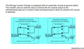
From my understanding, the inverter/charger should be bonding the output when not connected to shore power. When it is connected to shore power, the inverter/charger is meant to disconnect neutral-ground, thereby ensuring the neutral-ground aren’t bonded twice.
My guess is that the inverter/charger thinks that I have bonded the neutral-ground somewhere else in the system. Although would love to know if anyone else has had this issue? Or if anyone knows this product well enough to diagnose the issue?
My short term solution is to bond the neutral-ground in my distribution panel when I’m not connected to shore power. Then when I am connected to shore power, I’d disconnect them. It’s not an ideal setup as I’d have to connect/disconnect this every time - although I don’t plan on using shore power all that much anyway. Is there a better solution if I can’t figure out the code of the issue? I had the thought of adding a switch so I could easily bond and unbond. Someone in another forum told that if I do this, then I could risk issues due to unknown internal build quality and if it does have a reactive coupled centre tapped design will be compromised
Thanks!!


