diy solar

diy solar

Inverter Charger weird output when not connected to utility power (i.e., using the bypass)

jtown

New Member
Joined
Oct 22, 2023
Messages
15
Location
Courtenay, BC
UPDATE: I had another issue in my system that has now been resolved and have narrowed down my issues with the Inverter-Charger.

I recently installed my 3000W Renogy Pure Sine Wave Inverter-Charger.

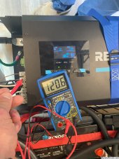
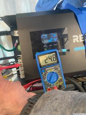
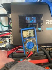
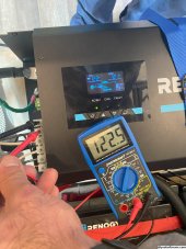
When I am not connected to shore power and the inverter-charger is not using the bypass function, I get the following readings from the output (photos #1-3):
- hot-neutral: 120V
- hot-ground: ~25V
- ground-neutral: ~25V

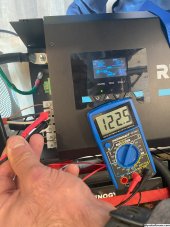
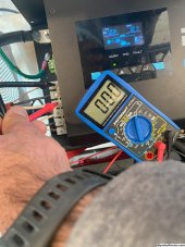
However, as soon as I am connected to shore power and the inverter-charger is using the bypass function to go directly to my AC loads without charging my batteries, then the output of my inverter-charger works great. I get the following readings (photos #4-6):
- hot-neutral: 120V
- hot-ground: 120V
- ground-neutral: 0V

It doesn't seem to matter if I turn the inverter-charger off/on or the whole system off/on. I get the same readings when the bypass function is being use and when it's not as described above.
Any help greatly appreciated.
 

Attachments

  • 1. 120V hot-neutralw bypass.jpeg
    1. 120V hot-neutralw bypass.jpeg
    918.6 KB · Views: 3
  • 2. 25V Neutral-ground wo bypass.jpeg
    2. 25V Neutral-ground wo bypass.jpeg
    854.8 KB · Views: 3
  • 3. 25V hot-ground wo bypass.jpeg
    3. 25V hot-ground wo bypass.jpeg
    864.9 KB · Views: 2
  • 4. 120V hot-neutral w bypass.jpeg
    4. 120V hot-neutral w bypass.jpeg
    864.4 KB · Views: 1
  • 5. 120V hot-ground w bypass.jpeg
    5. 120V hot-ground w bypass.jpeg
    883.3 KB · Views: 1
  • 6. 0V Neutral-ground w bypass.jpeg
    6. 0V Neutral-ground w bypass.jpeg
    855.4 KB · Views: 2
Last edited:
Asking a question, then provide the required info for an answer. (we cannot guess or see what you have through the wire)
Made & Model of your equipment.
Links to the products you have is ALWAYS Helpful.
A better description of your setup is valuable, diagrams & pictures are also worthwhile.
 
Asking a question, then provide the required info for an answer. (we cannot guess or see what you have through the wire)
Made & Model of your equipment.
Links to the products you have is ALWAYS Helpful.
A better description of your setup is valuable, diagrams & pictures are also worthwhile.
Edited please see a more detailed outline of my issue.
 
I'd say your shore power has a neutral-ground bond on it, your inverter is not bonded without the shore bond.
 
I'd say your shore power has a neutral-ground bond on it, your inverter is not bonded without the shore bond.
 
I'd say your shore power has a neutral-ground bond on it, your inverter is not bonded without the shore bond.
Any additional information to add on this? Not sure I fully understand how to resolve the issue on this specific inverter/charger.
 
At home I have a bonding jumper in my power panel that ties the neutral and ground together. With the two tied together there will be no voltage difference between them (same as you get on shore power). When my trailer is plugged into my 30A circuit at home, that bond carries into the service panel of the trailer and those neutral/ground will also be zero volts (because of the bond at the house panel). If I unplug from the house and plug into my generator and fire it up, things will be different. My generator (like most) does not have a neutral/ground bond so now my trailer is not bonded and my 3 light tester will show an open ground. If I plug a bonding plug that ties neutral and ground together, everything will again test fine because a bond has been created.

I followed the link to your inverter/charger and downloaded the manual. In the index it addresses automatic bonding on page 13, but when you go to page 13 there is nothing about bonding.

In my trailer I have a manual switch to transfer between my shore power and my inverter. When I switch to inverter, I have the switch contacts wired to create a neutral-ground bond (because the inverter doesn't have one).

I'll poke around a little to see if I can find any other info on yours (with internal transfer switch).
Awesome thank you so much I appreciated it!

I have the output of my inverter/charger connected to this Distribution Panel with my neutral and ground wires going to the respective spots on this distribution panel. Is it possible to bond the wires through this distribution panel? Or am I way off here?

Cheers
 
Short answer, no. A neutral-ground in that panel (same one that I have in my trailer) is just fine (and needed) when the inverter is making its 120VAC from the batteries. The problem comes up when the inverter is in pass-through mode when you have shore power. Now you have your bond in the WFCO panel plus another bond at the service point. Your bond creates a parallel path for the shore neutral because it now flows through the neutral wire AND the ground wire back to the service point.

I think that your inverter doesn't do the auto bonding. Renogy put the entry in the index but didn't develop the feature and didn't add the details on page 13 of the manual.
 
So it sounds like I need this to be sorted within the inverter itself? I've sent in a request to Renogy technical support team and waiting to hear back. Will update you when I hear back.

Thanks again for your help!
 
Back
Top