diy solar

diy solar

Installing Bluesea 6006 on/off switch location

geolboy

New Member
Joined
Feb 24, 2021
Messages
29
Hi Folks,
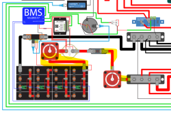
While building rv 12v pack in 4S2P LIFEPo4 cells 280ah (8 cells) I found that a best access physical location to place system wide kill switch would be right off the main POS first cell. Typical diagrams shows the switch located near main bus bar, after the main fuse and, in my case, a main contractor. Would it be acceptable to have it from the Cell+ post? I am also adding another one to the bus bar as well. I am just concern if the switch from the battery side can cause resistance for Contractor or REC BMS, that I will be using. If that is not advisable what other options do I have without moving it to the busbar? Thanks a lot in advance.
 
Ok, found one example, seems this is workable scenario, found this diagram from one of RecBMS affiliate sites.
1654050485972.png
If there are better suggestion I'll appreciate. Thanks!
 
I'd sure like to see the main battery fuse next to the battery, then everything else. If the battery shorts out you want the fuse to deal with the massive current, not the switch or anything else.
 
I'd sure like to see the main battery fuse next to the battery, then everything else. If the battery shorts out you want the fuse to deal with the massive current, not the switch or anything else.
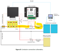
I would think that as well, but the Rec BMS manual places contractor before the fuse, there must be a reason for this? Here is snip from the doc. All I add is another switch to be able to pull the plug with a quick reach without getting to a tight closed compartment.. Thanks 1654056557319.png
 
There are just too many connections involved with extra switches and contactors and wow.
In my opinion both diagrams are wrong.
First thing! There must be a catastrophic fuse located at, or very near, the battery positive terminal. This fuse is first before anything else. All fuses must be at the battery end of each circuit. Each fuse will be sized to protect the ampacity of the wire.
Thanks for the advice, I'll try to get answer from REC BMS... I am curios as well, since they are one of the most recommended European BMS manufacturers for Victron/LifePO4 cell combos, especially in a marine environment, so they should know what they are publishing. There must be a reason they do that, would be good to know why.
 
Got an answer from REC folks: "You are right. Fuse before the contactor will also protect your contactor and battery in case there is some short current at the contactor pins for instance. We will change the schematics with the next manual version".

Thanks to all for the help!
 
Back
Top