diy solar

diy solar

Interfacing with Valence built in monitoring

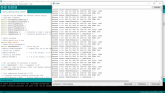
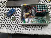
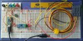
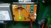
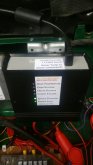
I did a first attempt in trying communication with the valence battery. But no luck, I loaded your code straight to the arduino Mega.
I see serial output on my scope before the RS485 ic, I use pin 2 to be able to transmit the messages. I noticed that on my arduino Mega the RX1 an TX1 are the other way around... I also have data on my A-B lines, but I got 5V signal blocks followed by 1.5V data so something is wrong in my converter circuit, I think.

It's possible the enable function is not working properly, it stays high when sniffing pin2.
I did comment out the following things because they don't make a change.

//#define hasAutoTxEnable // Comment this out if the underlying serial does not have automatic transmitterEnable
// Serial out to RS485
//#define RS485Tx 1 // 1 or 5 for Serial1, 10 or 31 for Serial2, 8 for Serial3
// Serial in from RS485
//#define RS485Rx 0 // 0 or 21 for Serial1, 9 or 26 for Serial2, 7 for Serial3

// RS485.setTX(RS485Tx);
// RS485.setRX(RS485Rx);

Tommorow is another day. :)
 
Yep another day is now!!!

So, yep forget my last message, It was late, feeling tired, sleepy eyes but I reviewed my scoop images one last time, and I didn't saw a differential signal... and the enable signal was not good. So I went a last time thrue the code and I saw the pin was not declared as output...
Wy wife will be angry not going to bed, but guess what?

So this solved the problem:
pinMode(enableRS485Tx, OUTPUT);

WOW AMAZING!! (sorry can't help it, words can't describe my feeling now!!)

Again, thank you!
 

Attachments

  • WOW AMAZING!.PNG
    WOW AMAZING!.PNG
    238.1 KB · Views: 63
Yep another day is now!!!

So, yep forget my last message, It was late, feeling tired, sleepy eyes but I reviewed my scoop images one last time, and I didn't saw a differential signal... and the enable signal was not good. So I went a last time thrue the code and I saw the pin was not declared as output...
Wy wife will be angry not going to bed, but guess what?

So this solved the problem:
pinMode(enableRS485Tx, OUTPUT);

WOW AMAZING!! (sorry can't help it, words can't describe my feeling now!!)

Again, thank you!

Yes, that's the one :)
I didn't notice this bug because the MCU (or maybe just the underlying hardware lib) that I'm using has automatic RS485 tx enable.

It should say:
Code:
    #ifdef hasAutoTxEnable
        RS485.transmitterEnable(enableRS485Tx);
    #else
        pinMode(enableRS485Tx, OUTPUT);
    #endif

I'll PM you over a newer version of my BMS code - it's evolved a bit since they other day. Now includes EEPROM event logging amongst other things. I'm planning to upload my code into the t3chN0Mad / OpenXPBMS repository on github, but still waiting for t3chN0Mad's agreement on this...
 
Thank you seb303, I've got the code running for 20 batteries on 1 bus and it's working great.
It's getting a mess to watch readings of 80 individual cells. But the balancing resistor's are at least working now.
I hope there will be enough sun to watch them getting balanced.
I'm going to have a peak in the new code now.
 
So I now monitor the batteries with an arduino MEGA, I think I will eventually design a new bms for it, the system is now protected with low/high voltage cut off, and a dump load in my 800liter water tank, controlled by an Arduino nano.
I made a small table test setup to test and debug the code, before expanding to the big system.
There was a point in life I had more then 20 batteries in service, but I ruined a few, but I have have kept the inner electronics and saved all cells I could.

Maybe be this is somewhat of topic but I included some pictures of my system at this moment.
You will see some pictures of the GUI, this is done with an RPI 3b+ and Nodered, it acts like a server an the pages are accessible from local network with the right IP address.

I still have some work to show all the readings, but don’t know if I will keep the current layout, it’s somewhat heavy or too much in one screen.Power system.PNGValence batteries.PNGValence battery cells.PNGBattery setup.jpg
 

Attachments

  • Test setup.jpg
    Test setup.jpg
    115.5 KB · Views: 27
Last edited:
Thank you seb303, I've got the code running for 20 batteries on 1 bus and it's working great.
It's getting a mess to watch readings of 80 individual cells. But the balancing resistor's are at least working now.
I hope there will be enough sun to watch them getting balanced.
I'm going to have a peak in the new code now.
That's a fairly sizeable setup you have there :)
I'm running only 2 batteries, just enough to power the 12V and small inverter of a campervan.

About the output mess: it's on my to do list to make the debug output neater and more compact. I also noticed that when my new code logs the battery values to the EEPROM (in the case of a change in state being triggered), it isn't logging all batteries so I need to fix that. And I'm working on a "Long term storage" mode where it will allow the batteries to rest, down to a certain SOC, rather than keeping them fully charged. I'll probably get time to work on these features tonight, so I'll ping over a new version then....

Code:
// To do
// -----
// Improve debug output to show multiple battery data in a neater table of values
// Log *all* battery data to EEPROM
// Log SOC to EEPROM
// Implement long term storage mode
// Add status flags for storage mode and when Min/Max SOC reached
// Function to reset CommsWarning (from serial console)
// Further research on threshold voltages, temperatures, Min/Max SOC
 
I also noticed that when my new code logs the battery values to the EEPROM (in the case of a change in state being triggered), it isn't logging all batteries so I need to fix that.
Actually thinking about your setup of 20 batteries, it would probably be better to log only the values of the 1 battery which triggered the change of status. Otherwise the EEPROM is going to get used up pretty quick....
 
It's not my intention to log the data with the arduino, if I would use the eeprom it will be for setting the parameters like under/over voltage, stuf like that.
And like you said, only safe big errors. If I log the data it will be on an sd card or the RPI with a database. But that is for the future,@ this moment I keep it basic.

But so far it's great, I just made the GUI so I can see all batteries in 1 screen, and another with all cells. If 1 cell is below 2.95 or above 3.6V it will show up red, so I can see it instantly. It's a bad day now, but if the sun comes from behind the clouds I get about 20A going in to each battery. And that's when I can monitor the deviations between the batteries, cells are all around 3.30V and are amazingly close to each other. But I won't see enough sun today, I hoped I could see the cells going to 3.5-3.7V today because that's were the interesting part (unbalance) will show itself... then I know how bad they are, or start balancing.

What I will do is make a capacity tester, so I can test every battery on a safe way. Even charge each battery with a CV, small CC power supply so they can slowly balance. Thanks to your and others efforts (I don't know of, yet) the internal bms will stay on 24/7.

Yes we are totaly off grid and in Belgium, it's a challenge. We have 416Ah AGM and 500Ah lifepo4 in a 48V system, but that are datasheet numbers. I don't know how much charge they still hold. There was about 7560Wp solar good for covering 66% of power consumption in the worst months (dec/jan) last winter, some panels were not good oriented. 3705Wp is waiting to go on the roof before winter lands, I hope this covers all consumption next winter. We will see, we have a small generator to help.

It's a hobby that got out of hand...
 
I'm familiar with hobbies that get out of hand ;)

I just PMed you a new version of the code.

The output is cleaner and has different debug levels, so you can turn off the continuous status output for example.

The EEPROM logging is also improved - it logs the battery data (V, T, SOC) only for the specific battery which caused a status change. Each log entry is 32 bytes, which gives up to 62 log entries on the chip I'm using before it wraps and starts overwriting the older entries. This should be plenty as it will only log on power-up or if there is a warning or shutdown situation (which ideally should never happen).

I guess I could use a board with an SD card for more detailed logging, but it seemed overkill for my situation. I've gone very minimal with the hardware (see attached photo). It'll fit on a small piece of strip-board with a few indicator LEDs. If any of the LEDs show errors then I can plug in a laptop and view the logs in the serial console.

P.S. The Valence XP cells should start balancing when they go above 3.360V and > 40mV above the lowest cell. But often the imbalance doesn't exceed 40mV when the cell voltage is this low, that's why you have to charge them a bit harder to see the balancing kick in.
 

Attachments

  • Prototype.jpg
    Prototype.jpg
    89.3 KB · Views: 40
I just created a github repository for my BMS...

Designed to provide monitoring of Valence XP batteries in order to:
  • Keep the Valence internal BMS awake so the intra-module balancing is active.
  • Provide a signal to a charge controller to disable charging in case of individual cell over-voltage or over-temperature.
  • Provide a signal to a load disconnect relay in case of individual cell under-voltage or over-temperature.
  • Provide warning and shutdown status outputs for over-temperature, over-voltage, under-voltage and communication error.
  • Provide basic event logging to EEPROM.
  • Have a mode for long term storage / not in use, where it will let the batteries rest at a lower SOC.
That's basically all the features I need so I'm not likely to extend it much, but I'm open for feedback.

I've tested it quite a lot and it seems to work well. I'm happy to provide advice to get it working, and bugfixes if needed.
 

Attachments

  • 20200910_080124_1599724533870_resized.jpg
    20200910_080124_1599724533870_resized.jpg
    65 KB · Views: 61
  • 20200910_083553_1599724496364_resized.jpg
    20200910_083553_1599724496364_resized.jpg
    77.1 KB · Views: 59
Yes, you could add a low temp cutoff to stop charging when very cold. But better if your charge controller has a sensor which can reduce the charging current say below 0C but only absolutely stop charging when say below -20C.

If you search the code for OverTemperature and OT, you'll see the bits of code that you'd have to duplicate, replacing OverTemperature with UnderTemperature, OT with UT, etc.
 
Regarding inter-battery balancing for series setups: in theory the batteries have the capability to do this themselves without any extra hardware, using the internal bleed-off resistor banks. But it's unlikely we will be able to crack this without analysing the communications of the actual Valence BMS hardware. Right now everything is based on analysis of the Valence Module Diag software communications, and this doesn't perform inter-battery balancing.

If you are implementing external active inter-battery balancing, then you probably don't need this internal functionality anyway.
I have the UBMS doing the intra battery balancing. But I guess you guys would probably need the external battery balancers in addition to what you're already doing.
 
Hi @seb303 Firstly, thank you very much for sharing your Arduino-XP-BMS project. It is much appreciated and got me into the world of Arduino and the excellent Teensy! (y)

I have built my Arduino-XP-BMS and was carrying out some hardware checks by changing some of the variable parameters/thresholds to force various Warnings or Shutdowns. This is when I found the PCBA temperature threshold values were being ignored. It would appear the current IF statement in the Over Temperature checks will always give a TRUE statement so the ELSE statements are never executed.

I have corrected the problem by changing the following code in the respective IF statements in lines 545 - 600 (v1.6 2020-10-18):
  • from if (j <= 4) { to if (j <= 3) {
  • from if (temps[j] to if (temps[4]
The image below shows the full code changes highlighted:
over temp.png

I would appreciate it if you could check and confirm this. Are there any other issues caused by these code changes?

Many thanks.

E.
 
Hi @seb303 Firstly, thank you very much for sharing your Arduino-XP-BMS project. It is much appreciated and got me into the world of Arduino and the excellent Teensy! (y)

I have built my Arduino-XP-BMS and was carrying out some hardware checks by changing some of the variable parameters/thresholds to force various Warnings or Shutdowns. This is when I found the PCBA temperature threshold values were being ignored. It would appear the current IF statement in the Over Temperature checks will always give a TRUE statement so the ELSE statements are never executed.

I have corrected the problem by changing the following code in the respective IF statements in lines 545 - 600 (v1.6 2020-10-18):
  • from if (j <= 4) { to if (j <= 3) {
  • from if (temps[j] to if (temps[4]
The image below shows the full code changes highlighted:


I would appreciate it if you could check and confirm this. Are there any other issues caused by these code changes?

Many thanks.

E.

Thanks for spotting the bug! It is indeed ignoring the PCBA values.

The temps[j] can stay as it is, only the if statement to fix. I did it like this:

1605559974917.png

I'll upload the fix to github now...

Cheers,
Seb
 
Thanks for spotting the bug! It is indeed ignoring the PCBA values.

The temps[j] can stay as it is, only the if statement to fix. I did it like this:

View attachment 27703

I'll upload the fix to github now...

Cheers,
Seb

Actually, this would probably be better:
if (j < NumberOfCells) {
In case of batteries with other numbers of cells.
 
Actually, this would probably be better:
if (j < NumberOfCells) {
In case of batteries with other numbers of cells.

Thank you for the prompt response. I have edited my code as you suggested above and all tested fine. (y)

Thanks again for sharing your project. :)
 

diy solar

diy solar
Back
Top