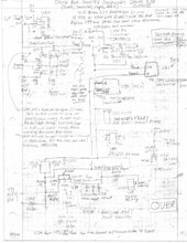
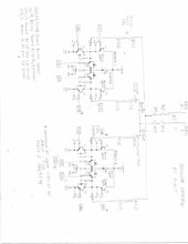
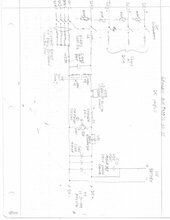
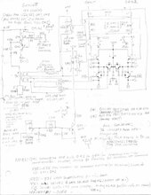
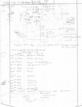
I am trying to repair a Growatt MIN11400TL-XH-US. I haven't been able to find a schematic for it, but I do have this generic block diagram, courtesy of RCinFL.

I found several damaged IGBT's in the PWM output section, again with thanks to RCinFL who helped with the diagnosis. However, there is visible damage in another part of the circuit board which is in the PWM circuit as far as I can tell, but seems like it shouldn't have been damaged. I say 'seems like' because I don't know exactly how the circuit works.
The damage is in an area of the board that contains a TI 2845B current mode PWM controller. Here is the datasheet. The specific damage is that the board swelled, breaking at least one via and popping off two surface mount resistors. There may be other damage. Here is a picture after my repair to the damaged via (the PWM IC is on the opposite side):

My first question is how this part of the circuit could have been damaged. It seems like it is upstream of the Opto-PWM gate drivers and they seem ok (there are a total of 12, one for each IGBT, and they are not shorted from the input side to the output side).
The next question is if anyone has a typical schematic that would show how a PWM controller would be configured with Opto-PWM gate drivers? I've looked for application guides on this and similar PWM controllers with no luck.
The last question has to do with identifying two components on the board so I can test them and/or replace. They are the two 4 terminal components labeled Q41 and Q42 and are right next to the PWM controller.

It seems like they would be transistors, but from the markings and the dimensions of the part, I'm not sure. The markings on one (Q41) says M 304 Y, but the closest I can find on google is a PBSS304PZ. Datasheet here. The markings on the other part in question (Q42) are N 30? Y where the ? is unreadable). Could it be that one is a PNP and the other NPN? I'm confused because the datasheet for the PBSS304PZ shows that the part measures 6.7 x 7.3 mm, whereas the part on the board measure 4.3 x 5.4 mm and I can't find anything closer.
Thanks for any suggestions!
I found several damaged IGBT's in the PWM output section, again with thanks to RCinFL who helped with the diagnosis. However, there is visible damage in another part of the circuit board which is in the PWM circuit as far as I can tell, but seems like it shouldn't have been damaged. I say 'seems like' because I don't know exactly how the circuit works.
The damage is in an area of the board that contains a TI 2845B current mode PWM controller. Here is the datasheet. The specific damage is that the board swelled, breaking at least one via and popping off two surface mount resistors. There may be other damage. Here is a picture after my repair to the damaged via (the PWM IC is on the opposite side):
My first question is how this part of the circuit could have been damaged. It seems like it is upstream of the Opto-PWM gate drivers and they seem ok (there are a total of 12, one for each IGBT, and they are not shorted from the input side to the output side).
The next question is if anyone has a typical schematic that would show how a PWM controller would be configured with Opto-PWM gate drivers? I've looked for application guides on this and similar PWM controllers with no luck.
The last question has to do with identifying two components on the board so I can test them and/or replace. They are the two 4 terminal components labeled Q41 and Q42 and are right next to the PWM controller.
It seems like they would be transistors, but from the markings and the dimensions of the part, I'm not sure. The markings on one (Q41) says M 304 Y, but the closest I can find on google is a PBSS304PZ. Datasheet here. The markings on the other part in question (Q42) are N 30? Y where the ? is unreadable). Could it be that one is a PNP and the other NPN? I'm confused because the datasheet for the PBSS304PZ shows that the part measures 6.7 x 7.3 mm, whereas the part on the board measure 4.3 x 5.4 mm and I can't find anything closer.
Thanks for any suggestions!