taylorbourne
New Member
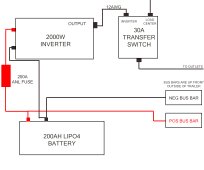
Looks like I'm almost ready to start my solar setup. I'm trying to post this schematic in a few places to verify my research has been correct. I've decided that since I have a brand new generator to recharge batteries (and a 160W suitcase setup) I should first add a new battery and set up my inverter. Note – inverter is extremely important to my wife in order to watch TV at night. Wondering if I can get a quick sanity check on my wiring diagram.
The plan is to mount all of this in the pass-through of my travel trailer, with the option to add a solar controller in the future. My unit is already prepped for solar/inverter, so I've already scoped out where the pos/neg from the panels on the roof route down near the pass-through, and I'll be able to pull them in with no problem. I think the hardest part here would be to drill the hole in the floor of the pass-through to run cables back to the POS/NEG battery bus up front behind the current batteries.
Note that the Romex coming from the load center is a loop in my pass-through currently – so I'll be cutting that and routing it through the transfer switch.
For wire size I'm thinking of 12AWG Romex style from the inverter to the transfer switch, then 1/0 for the rest. Is that overkill?
Thank you! (schematic attached to this thread)