diy solar

diy solar

Is it normal for LiFePO4 batteries to warm up while charging?

lawful-nervous

New Member
Joined
Aug 17, 2022
Messages
34
TL;DR: Batteries are getting warm (34°C) but not hot. How warm is too warm and are my batteries safe to use?

---

Charging 2 206aH 12v SOK batteries using the factory settings on the Victron MultiPlus.

Both the batteries and the inverter are a little warm to the touch, but not so hot that I can't comfortably touch them. ABC-BMS app says the batteries are at 34°C.

The positive cables in the batteries (0/1 gauge, less than a foot in length) are similarly warm to the touch. The negative cables and the cables to the inverter are all cool.

The batteries were recently deeply discharged from being in storage too long. I managed to revive them but am a little concerned about their safety.

Is this normal? How warm is too warm?

(Sorry if this has already been asked before. Google was only giving me results about heated LiFePO4 batteries or batteries that got very hot.)
 
Last edited:
TL;DR: Batteries are getting warm (34°C) but not hot. How warm is too warm and are my batteries safe to use?

---

Charging 2 206aH 12v SOK batteries using the factory settings on the Victron MultiPlus.

Both the batteries and the inverter are a little warm to the touch, but not so hot that I can't comfortably touch them. ABC-BMS app says the batteries are at 34°C.

The positive cables in the batteries (0/1 gauge, less than a foot in length) are similarly warm to the touch. The negative cables and the cables to the inverter are all cool.

The batteries were recently deeply discharged from being in storage too long. I managed to revive them but am a little concerned about their safety.

Is this normal? How warm is too warm?

(Sorry if this has already been asked before. Google was only giving me results about heated LiFePO4 batteries or batteries that got very hot.)
Normal.
 

Attachments

  • Screenshot_20230808-153216.png
    Screenshot_20230808-153216.png
    150 KB · Views: 26
Sounds OK, they will warm on charge or dischage a bit. But will depend hugely on charge rate, ambient temperature and airflow.
 
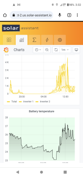
The chart only shows 4 degrees rise.
34C might be 9 degrees rise.

9 degrees should be OK, but is this operating at max current?
If there is a poor connection, things could get worse. So worth investigating.

Positive cable hot and negative cool is suspicion, unless something like shunt is acting as a thermal break or heatsink.
Check temperature on both sides of shunt (if any; likely inside SOK). Check cables between batteries (series or parallel?)

Unless there is a reason for the two cables to be different temperatures, I'd take the difference as indication of a problem for the hotter one.

Using IR thermometer, map temperature from one end to the other of each cable. See which direction heat is flowing, what is hottest, to find source. Maybe there is a poor connection.
Thanks for the reply! I turned them off as soon as I noticed them getting warm, but I will turn the inverter on again and try to get some temperature readings.

They're wired in series.

Also, do you know if it's okay to be using the victron MultiPlus factory settings for LiFePO4? The voltage and amperage fall within the charge parameters for my batteries.
 
All Li batteries have a suggested charge and discharge suggested continuous rate.

It is not one number for every LiFe battery.

When possible, I try to run LiFe batteries at 50% of the supplier suggested continuous number on the data sheet.

What is the recommended amps charge rate on your SOKs?

What is the charge rate of your inverter / charger?

They are prismatics not cylindricals. This is good for density, not as good for dissipating heat.
 
Last edited:
It is normal. Heating up depends on the losses. Charging with 100A generates roughly 10W losses per cell in pretty good battery build scenario. So these are 40W heating up your battery. This is just an example, but it gives the idea about what should you expect.

Same goes for discharging. It will also heat up the battery.

The cable heating up would be pretty normal thing. It also has resistance and the current going over it generates losses. The losses heats up the cable.

Check the resistance of each component to see what is normal. Or just check the voltage drop with multimeter when decent current is going through the components.

Regarding what is normal - 35C is pretty OK. The lower you stay - the better. I'm aiming at temperatures between 15C and 35C.

And regarding the cells being deeply discharged - measure the internal resistance and if you see major deviation, than there is a cell that has failed. If the IR is pretty close to the initial one and no obvious signs of cell issues are visible you are likely lucky, and there won't be issues with the cells.
 
Last edited:
All Li batteries have a suggested charge and discharge suggested continuous rate.

It is not one number for every LiFe battery.

When possible, I try to run LiFe batteries at 50% of the supplier suggested continuous number on the data sheet.

What is the recommended amps charge rate on your SOKs?

What is the charge rate of your inverter / charger?

They are prismatics not cylindricals. This is good for density, not as good for dissipating heat.
The MultiPlus charges at 50amps. The recommended amps for charging for my batteries is 40, but the max is 70.
 
It is normal. Heating up depends on the losses. Charging with 100A generates roughly 10W losses per cell in pretty good battery build scenario. So these are 40W heating up your battery. This is just an example, but it gives the idea about what should you expect.

Same goes for discharging. It will also heat up the battery.

The cable heating up would be pretty normal thing. It also has resistance and the current going over it generates losses. The losses heats up the cable.

Check the resistance of each component to see what is normal. Or just check the voltage drop with multimeter when decent current is going through the components.

Regarding what is normal - 35C is pretty OK. The lower you stay - the better. I'm aiming at temperatures between 15C and 35C.

And regarding the cells being deeply discharged - measure the internal resistance and if you see major deviation, than there is a cell that has failed. If the IR is pretty close to the initial one and no obvious signs of cell issues are visible you are likely lucky, and there won't be issues with the cells.
Thank you very much! This is very helpful advice and information
 
"The positive cables in the batteries (0/1 gauge, less than a foot in length) are similarly warm to the touch. The negative cables and the cables to the inverter are all cool."

This is the difference that seems worth investigating. There has to be a reason. Might be a bad connection, or might be different thermal path from cells to positive vs. negative terminal.

The MultiPlus charges at 50amps. The recommended amps for charging for my batteries is 40, but the max is 70.

Vicron SCC with Cerbo can regulate charging to lower current while supplying more for inverter.
If MultiPlus is a hybrid, can probably do that internally.

40A or 70A is relatively low for larger LiFePO4 cells. What capacitor are yours?
Do you have charge current vs. temperature specs? If it will sometimes be cold, easiest solution could be reduced charge current all the time. Probably still plenty of hours in the day to fully charge.
 
The MultiPlus charges at 50amps. The recommended amps for charging for my batteries is 40, but the max is 70.

You are in the right range.

Keep in mind that the LiFe battery market is incredibly competitive. The data sheets and specs are often pushing it to get an order.

There is nothing harmful about dialing it back a bit. Maybe try cutting it back to 20 - 30 amps and see if things run a bit cooler?
 
Thanks for the reply! I turned them off as soon as I noticed them getting warm, but I will turn the inverter on again and try to get some temperature readings.

If it was only minutes to get 9 degree rise, could get much hotter operating continuously. Copper has a lot of thermal mass.

Unless you have a really sensitive IR camera (like one somebody described showing warmed water in a pond from a duck paddling by), need to give time for watts to develop into a thermal contour.

But voltage drop develops immediately. Use a DMM to check voltage drop between battery terminal and the cable terminal, etc.

It may be that battery dissipates more power charging than discharging. Wires will be equal in either direction of current flow. BMS has MOSFETs with some resistance, and separate FETs for charging vs. discharging path. Likely both NPN but wired in opposite directions, so power dissipation at drain dumps heat into cables in one case, first cell in the other.

BMS FETs - that could be the reason!
 
And regarding the cells being deeply discharged - measure the internal resistance and if you see major deviation, than there is a cell that has failed. If the IR is pretty close to the initial one and no obvious signs of cell issues are visible you are likely lucky, and there won't be issues with the cells.
I tried to figure out how to measure the internal resistance and I don't have the right equipment. All I have is a multimeter and a bench power source. Do you have any recommendations on what device I should by to check internal resistance?
 
"The positive cables in the batteries (0/1 gauge, less than a foot in length) are similarly warm to the touch. The negative cables and the cables to the inverter are all cool."

This is the difference that seems worth investigating. There has to be a reason. Might be a bad connection, or might be different thermal path from cells to positive vs. negative terminal.
I disconnected the batteries from each other and discovered that one of them was at 0% and the other was at 83%. I thought I had revived it, but the BMS of the battery at 0% mush have shut down and it was not accepting charge. Could this be the cause of the hot leads?

40A or 70A is relatively low for larger LiFePO4 cells. What capacitor are yours?
Do you have charge current vs. temperature specs? If it will sometimes be cold, easiest solution could be reduced charge current all the time. Probably still plenty of hours in the day to fully charge.
I'm not sure about a capacitor, unless you meant capacity? They're 206aH each.

The ABC-BMS doesn't appear to store data or have nice graphs like I've seen other people post, unfortunately.
 
If it was only minutes to get 9 degree rise, could get much hotter operating continuously. Copper has a lot of thermal mass.
It took a couple of hours to get warm.

Unless you have a really sensitive IR camera (like one somebody described showing warmed water in a pond from a duck paddling by), need to give time for watts to develop into a thermal contour.
But voltage drop develops immediately. Use a DMM to check voltage drop between battery terminal and the cable terminal, etc.
That makes sense. I don't have fancy equipment so I was going to try to use a thermometer ?

It may be that battery dissipates more power charging than discharging. Wires will be equal in either direction of current flow. BMS has MOSFETs with some resistance, and separate FETs for charging vs. discharging path. Likely both NPN but wired in opposite directions, so power dissipation at drain dumps heat into cables in one case, first cell in the other.

BMS FETs - that could be the reason!
I am unfamiliar with the acronyms MOSFET, FET and NPN. I'll look into those so that I can understand this a little better.
 
I disconnected the batteries from each other and discovered that one of them was at 0% and the other was at 83%. I thought I had revived it, but the BMS of the battery at 0% mush have shut down and it was not accepting charge. Could this be the cause of the hot leads?

In series, I would expect current to flow in one only if it flows in the other.
You need to charge each to same SoC. 83% is only an estimate. I would charge to some higher equal voltage, like 3.5V or so per cell (14V per battery)

I'm not sure about a capacitor, unless you meant capacity? They're 206aH each.

Capacity. So 70A is 0.33C, 40A is 0.2C, pretty conservative rates.

The ABC-BMS doesn't appear to store data or have nice graphs like I've seen other people post, unfortunately.

So that's what's inside SOK?

It took a couple of hours to get warm.

At a moderate charge rate. Wonder what it does at high discharge rate (100A or 200A allowed?)

That makes sense. I don't have fancy equipment so I was going to try to use a thermometer ?

Harbor Freight and others sell non-contact IR thermometers. Some are $12 to $25.
IR cameras are nice, but pricy for good ones.

I am unfamiliar with the acronyms MOSFET, FET and NPN. I'll look into those so that I can understand this a little better.

Transistors. My field. I have an idea of what BMS circuit looks like and I'm familiar with where heatsinks are attached to transistors, so I could imagine BMS heating positive cable or heating one cell depending on direction of current flow.

You may not have to think in terms of transistors so long as you're working with boxes.

What we need is to hear from others with lithium batteries and SOK batteries, whether they see different temperatures.
 
I tried to figure out how to measure the internal resistance and I don't have the right equipment. All I have is a multimeter and a bench power source. Do you have any recommendations on what device I should by to check internal resistance?

Some BMS report IR. Can you talk to yours?

I suppose the battery boxes are sealed. If you had access to cell terminals, voltage drop of a cell (no load vs. load) divided by current being drawn would give IR.

You could approximate that externally, voltage drop of entire battery then divide by 4 cells. But BMS resistance would be included in the measurement.
 
We run mostly 48V 280Ah batteries out here ... when the surge pumps kick on -- and these are some serious surge pumpts -- but they draw at a 2C rate -- and then of course when the solar can't keep up the generator kicks in and feeds it back at a 2C rate ... so basically for about 30 minutes you can cook your lunch on the batteries -- and so far we have had zero concerns or issues ... of course the poor BMS looks and smells like its gone through hell and back BUT the batteries all seem fine -- We do though have the surge pump batteries strapped / banded with metal bands to keep any abnormal bulging from occurring - but again -- after 2 years - everything still seems fine on all of these systems ...

Would I do 2.1 C ... oh hell no ... LOL
 
Why charge at 2C?
Just because charger was sized to keep up with pump, and system doesn't charge at slower rate?

If BMS is the only thing struggling, I'd think contactor would be the way to handle 560A.

But maybe your application has a 2 year time horizon. Who knows what oil will be worth next year.
 
Some BMS report IR. Can you talk to yours?
The ABC-BMS is th app SOK developed for their Bluetooth BMS. I have not dug into how much I can gather from that, but there is no apparent IR reading.

I suppose the battery boxes are sealed. If you had access to cell terminals, voltage drop of a cell (no load vs. load) divided by current being drawn would give IR.

You could approximate that externally, voltage drop of entire battery then divide by 4 cells. But BMS resistance would be included in the measurement.
Okay, I though I needed either an appropriately sized resistor or a purpose made IR tester.

I want to make sure I did this right:

I took a string of LED lights to use for my load. I couldn't get a reading on the current draw of the LEDs when it was hooked up to my battery, so I set the voltage of my bench power source to match the voltage of the battery as precisely as possible. It read at 0.62a.

Then I measured the cells individually with and without the load.

For the first cell I got 3.157 without and 3.155 with. (all the other cells were similar).

So that would be (3.157-3.155)÷0.62=0.0032

Is that correct?
 
Back
Top