diy solar

diy solar

Is my off-grid system safe?

lherman-cs

New Member
Joined
Feb 9, 2022
Messages
7
Hi all, this is my first time designing a solar off-grid system. I did a lot of research system and have sketched up my plan in DrawIO. Would greatly appreciate anyone to scrutinize the design! The design goal is to create a safe system and NEC 2017 code compliant.
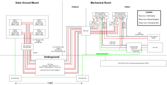
solar.drawio.png

* I am especially shaky with grounding and lightning protection
* Do I need to have SPDs to protect my system from lightning surges? Isn't earth grounding supposed to solve this?
* In the design, I have ~125 feet grounding wire in the ground. I'm concerned that this is too long for a grounding wire that it becomes an ineffective lightning protection.
* Do I have to have a circuit breaker between solar panels and solar charge controller?

Great resources that helped me to get to this version:
* Awesome grounding docs from FilterGuy (thanks a lot!): https://diysolarforum.com/resources/grounding-made-simpler-part-1-ac-houshold-grounding.157/
* Amazing video about SPD fundamentals:
* Will's EG4 setup: https://www.youtube.com/watch?v=mzZR6SWonrY
* and many others...


My equipment spec sheets (attached for everybody convenience):
* Inverter: EG4 6500 EX-48
* Battery: EG4 Lifepower4 48v nominal @100ah
* Solar Panel: Ureco FAK445C8G
 

Attachments

  • EG4 6.5 Spec Sheet-1.pdf
    416.5 KB · Views: 4
  • battery-eg4-spec-sheet.pdf
    5.4 MB · Views: 3
  • solar-module-ureco-fak445c8g-4.pdf
    2.4 MB · Views: 6
Welcome!

Looks like you've put a ton work into your design so far.

I saw a few things but only looked as far as the IMO's right before the inverters.
-I believe you'll need two IMO four poles at the array.
-I don't drive a ground rod at the array and like to use SPD before the wires get to any electronics.

Hopefully others will take a look and comment.
 
Nothing will completely protect from a direct lightning strike. Generally best to stick with a single ground rod unless something says two are needed.

Generally no breaker is needed from the panels to the inverter. The solar is self limiting and will not over amp the wires. Good idea to have a cut-off switch for service. The switch is required for a grid-tie system.

Any reason to avoid split phase service to the main panel? Not sure those inverters support split phase configuration. Some appliances are more efficient at 240v such as a mini-split air conditioner.

Battery fuse should be close to the battery. May only need one fuse to serve both. Right now it shows up to 400 amp protecting a #1 wire.
 
Grounding is good but grounding alone is not sufficient for lightning surge as I understand it. I use several lightning arrestors - https://www.altestore.com/store/enc...rotection-device-300vdc-and-120240-vac-p9042/ - (surge protection) wired at the combiner boxes. This takes care of outside the house but some have suggested inside as well.

Drawing wise, couple of quick comments...
- I don't see quick disconnect outside / near the solar panels. My jurisdiction requires this + labels with voltage/amps for firemen.
- As mentioned above, my electrician used house ground for my PV array grounding. I'm no expert and there are many opinions but when you do multiple grounding rods there's a chance you can get current between the 2 grounding points. A single ground seems common.

Safety wise....
I've been running a 13kw PV array producing 18,000kwh / year off-grid solar for 4+ years now and I've had the following issues in order of safety concerns....
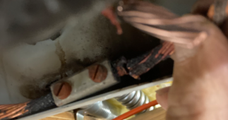
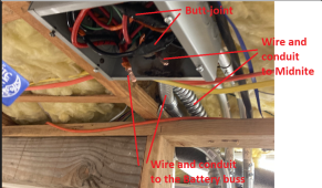
- Melted/burned butt-join. The electrician did a butt-join on 4awg / 80a wiring between the Midnite Classics and the battery bus and one of them burned / melted thru. Fortunately it was in a proper metal junction box so nothing was ignited around it. **Conduit / Junction boxes are good for safety.
- Had a Go-Power 120v@30a ATS fail with melted wiring (for some reason - not sure to this day) but again was inside the box. **Boxes are good.
- I've had a few overloads but proper circuit breakers tripped each time - protecting wire. **Proper breakers/fusing is good.

Otherwise, it's just been a few annoying things - nothing dangerous.

Some thoughts...
- Suggest all UL/ETL components/equipment + NEC Code for wiring / conduit / boxes / breakers-fuses. **Sounds like you're already committed to this.
- Consider Arc-fault protection on the PV array(s). I use Midnite Classic charge controllers and they have arc-fault protection built-in but I believe there are stand-alone breakers or solutions for this. They also have DC GCFI built-in - another suggestion.
- Good overall system monitoring - BMS(Battery bank) metrics, maybe some temp probes on warm wiring, power production stats, etc - so you can see trends or anomalies. For example, in the butt-join case I actually had a temp sensor in the metal box and it recorded overly hi temps (90C/194F range) 5 days before it burned thru... but I just didn't notice. I've since added 'active alerts' on any temp probe data that reports over 60C/140F.
 
Last edited:
Nothing will completely protect from a direct lightning strike
It’s always been a mystery to me that people want to rely on a 8ga wire or a $15 device or standing on one’s head while driving a ground rod for lightning protection. Any lightning capable of doing damage and a lot of lightning that can fry the tv with no visual damage isn’t really going to care that much after traveling through as many as 20 miles of atmosphere before splitting the oak tree in the side yard and killing all your LEDs in the house.
Boxes are good
I hate that convenient-looking affordable boxes preloaded with devices… are plastic.
 
Wow. I didn't expect to get these many responses. Thank you!

I hope that I address each response in this reply.

@OzSolar

  • 2 IMO four poles at the array
    • I put only 1 IMO Disconnect because I personally think that it's more organized. I think about disconnects as switches to service the equipment, the whole array is the equipment in this case.
    • Why do we need 2 IMO four poles? Is there a specific requirement from NEC 2017?
    • Currently, this is the specific IMO model I'm thinking to get, https://practicalpreppers.com/product/imo-4-pole-32-amp-dc-disconnect/. Is this not good for 4 strings?
  • Don't drive a ground rod at the array and like to use SPD before the wires get to any electronics.
    • Having 1 ground rod at the main house makes sense. The grounding wire from the solar panels is going to be bare and buried in the ground. So, I think there will be enough earth contact in case of a lightning inducing the equipment.
    • From my reading, SPDs sound like fantastic devices against transient voltages! But, why don't we have SPDs in every house? I feel like I'm either misunderstanding SPDs or missing some information about how houses handle transient voltages.

@time2roll

  • Nothing will completely protect from a direct lightning strike
    • How about Air Terminal Lightning Protection Systems? I notice that these systems are common only for tall buildings. But, I'm curious if it's needed for my house since it's in a rural area so there's no other houses around.
  • Any reason to avoid split phase service to the main panel?
    • Yes, because it's a small house, 16x32. I'm planning to get the Mr.Cool 12k BTU with 120v, which should be enough for the house size. Other appliances also only require 120v because there's no much space so the appliances get scaled down. For example, we will have an induction cooktop, but a portable one. We will have a washer dryer, but the combo one that you can find in studio apartments.
    • Another reason is that the EG4 all-in-one inverters (and many other all-in-one inverters) can do load balancing equally between the inverters in 120v system, where as 240v system will have an unequal load depending on the usage per leg.
    • Last reason is that 120v can be powered with a single EG4 inverter, whereas 240v requires at least 2 EG4 inverters. This is good because I'm planning to use this system to power 2 buildings: main and guest houses. The current drawing is only used for the guest house. I want to live in the guest house for a while until I have enough money to build the main house. Later, I can picture that the load of the guest house will decrease significantly so I can remove 1 inverter and give it to the main house, which won't be possible if I have 240v.
  • Battery fuse 400 amp protecting a #1 wire (I think you meant 240amp protecting a #1 wire)

@OffGridInTheCity

  • Grounding is good but grounding alone is not sufficient for lightning surge as I understand it
    • Same reply to @OzSolar, why do houses not have SPDs? These seem to be very important devices from my understanding.
  • I don't see quick disconnect outside / near the solar panels
    • IMO 4 Pole DC after the solar array is meant to be the quick disconnect outside/near the solar panels. Is there a specific equipment requirement for a quick disconnect?
  • Single vs double grounding rods:
    • From my understanding, both options are fine as long as they're connected to a single common grounding electrode, which seems to be common in multiple building situations (according to
      ). Since the grounding wire from the solar array is connected to the house's grounding electrode and it never goes through solar equipment, lightning surges will stay under the ground and it won't create a ground loop.
  • Melted/burned butt-join
    • What was the cause?
    • Thank you for the general tips!
      • Conduit / Junction boxes are good for safety, contain fire hazard.
      • Proper breakers/fusing is good, stop overloading current.
 
@OffGridInTheCity

  • Grounding is good but grounding alone is not sufficient for lightning surge as I understand it
    • Same reply to @OzSolar, why do houses not have SPDs? These seem to be very important devices from my understanding.
I guess I just assumed it's because PV Arrays (with metal rails) are natural born lightning rods whereas a house (like mine) doesn't have anything on the roof (or exterior) to draw a lightening strike into the wiring.

But its a really good question. Maybe someone will comment in more detail :)

  • I don't see quick disconnect outside / near the solar panels
    • IMO 4 Pole DC after the solar array is meant to be the quick disconnect outside/near the solar panels. Is there a specific equipment requirement for a quick disconnect?
The idea is for fire-fighters to be able to disconnect PV power before entering a house.
The specifics were laid out in my city's permit / code process. It include an outside sticker (for example) listing the voltage and amps.
So - I'd say besides the common sense fire-fighting issue, the rest would be up to you're local jurisdiction codes.

  • Melted/burned butt-join
    • What was the cause?
It overheated - perhaps arced? I don't know. This was installed by the electrician. My main point is that NEC code (conduit, boxes) can serve a good purpose and I offered my experience as a real-world reason t use them :)
 
I think so long as you don't let an unsupervised toddler in your electrical cabinet, things should be pretty safe.

I have a 3.5yr old son. He let the magic smoke out of a couple of charging cables once (12v), lesson learned :)
 
Why do we need 2 IMO four poles? Is there a specific requirement from NEC 2017?
You have to disconnect negative as well since it isn't bonded to ground so a four pole will only be good for two strings. (someone else will jump in add clarity if I'm wrong))
 
You have to disconnect negative as well since it isn't bonded to ground so a four pole will only be good for two strings. (someone else will jump in add clarity if I'm wrong))
because there could still be a potential “circuit” if pos(+) neg(-) are not both disconnected is my understanding.
 
This isn’t a good plan imho especially if tied to the ground rod at the house
I disagree, I think grounding the panels with their own separate rod is a great idea. It's a different ground for a different purpose, mainly to bleed off static and provide some protection from a nearby lightning strike.
However this ground should absolutely not be connected to a ground at the house.
I would always install circuit breakers between the panels and the charge controller.
 
The design goal is to create a safe system and NEC 2017 code compliant.
Review of the wire sizing and protection:
PV to Inverters DC power distance 125 feet plus risers at each end, lets assume 140 feet, max Amperage based on the 8 PV 11.83A array and voltage indicated is 483vDC, using a typical online DC wire size calculator, and allowing for 25% head room (you didn't indicate cold weather temps, the PV panels will have a Delta for cold temps.) I used 483vDC , 15A and the calculater spits out 14AWG so 10 AWG is plenty/ may be suitable for 25-30A.
In my region a DC rated PV disconnect is required at the exterior of the building where the PV DC enters (for fire-fighters) although not required to be fused at this location, it is a sensible place for a disconnect for maintenence. Most inverters require fusing/breaker between the PV and the inverter - 15A would be suitable from your data. Surge protection was already discussed.

AIO to Battery Rack DC power - you don't indicate the distance lets say it is short, I used 10 feet for calculations. Your design indicates '60 volt 200A' for each AIO. The DC wires here are two way traffic, during PV charging power is flowing to the batteries and during use of the batteries power if flowing from the batteries where the voltage will sometimes be drawn down to say 48vDC. In both cases, from your bus bar to the batteries carries twice the amperage of the AIO to the bus bars.
PV array #1 & #3 combined are 7840W plus the delta in cold weather, likely the AIO will cut this off at 8kWmax (i didn't check the spec) charging voltages are typically 62vDC which would be 126.5A and the DC wire calculator spits out 1AWG wire required (based on up to 40-feet wire length). so far so good.
Now we consider the batteries feeding the AIO x 2 units, noted on the drawing as 60vDC 240A up to the bus, and perhaps 120A from the bus to each AIO. The calculator indicates 1 AWG cable size for the bus to EACH AIO this would be a good place for 125A T-class fuses. You can check what over-load the AIO can carry, you may want to up-size to 1/0 cable and 150 T-class fuses.
Now consider the bus to the battey rack -here your conductors are carrying 240A and when the battery is drawn down to say 48vDC this results in exceeding the capaciy of even a 4/0 cable. You could use twin runs each on the neg and pos of 3/0 or look for 350MCM cable and use 300A T-class fuses to protect these conductors. The other option is to run the 1AWG from each AIO to the bus bar on the battery rack tower, and fuse each with 125A t-class fuses. This would be a good place for a a pair of dedicated DC rated two pole breakers between the AIO and the battery rack so you can disconnect for service - or in case of a fire, rather than turning off each battery rack one by one. In my location a single-throw dedicated 2-pole/4-pole disconnect is required between the Energy Storage System (ESS) and the Inverters for fire-fighters use, clearly indicated with signage.
Lastly the AIO's to the Load centre (panel). From the diagram you indicate 130A 120vAC, now we use a AC calculator and since the power is supplied by two AIO each will be limited to perhaps 54A (ck the manual) and the AC wire size calculator spits out 4AWG for 65A but 6AWG for 54A - the drawing indicates 1AWG although you will need to see if the AIO terminals are suitable. I recall having difficulty working with 6AWG in my AIO units.
Hope this helps.
 
However this ground should absolutely not be connected to a ground at the house.
But a fault - since the batt(-) should be connected at the N-G bonding location- could create a circuit.

I used to be of the opinion that an off-grid should not have a AC ground rod but I’m not so sure anymore. And if I’m not mistaken NEC indicates for a ground rod at the house. The unexpected fault is what keeps revolving in my mind.

Proper, careful wiring practices prevent fires and insure dependable systems.
Grounding keeps us from electrocuting ourselves- or others- to death.
 
Last edited:
@OffGridForGood

PV to Inverters:
  • I did include the delta in VOC for cold temperature in the diagram. Unfortunately, I don't think I did a good job in making that clear in the box. It's mentioned as "438.33 @0F". This is already the VOC of the solar array using the official spec sheet at 0 degree fahrenheit.
  • I used this formula to figure out the cable sizing (hopefully it can help to clarify how I came with 10 AWG):
    • VD = I * L * 2 * R / 1000
      VD is voltage drop
      I is the load current in ampere (A).
      L is the wire distance on meters (m) or feet (ft). (one way)
      R is the wire resistance in Ω/km or Ω/1000ft.
  • Then, I used my desired parameters with future proofing and high performance in mind:
  • L = 150ft
    R = 1.0200 Ω/1000ft (based on DC resistance at 20 degree Celsius from NEC2017)
    I = 36a (inverter maxed at 18a, but this is future proofing for a bigger inverter like sol-ark)
    V = 290v (operating voltage)

    VD = 36 * 150 * 2 * 1.02 / 1000 = 11.016v
    VD% = 11.016 / 290 * 100 = 3.8% (I'm still happy with the voltage drop, there's enough headroom for other kinds of voltage drop in the overall system)
  • I also designed it for performance because I think it's one of main bottlenecks in the system. With the current amperage rating (18a), this line's voltage drop should be 1.9%. (which hopefully the overall voltage drop coming from just the cables, including AC lines, is still under 5%)
  • That makes sense to put the disconnects outside for firefighters. I'll check with the local authority.
  • What would be the wiring order for the circuit protection? I'm thinking something like PV -> Disconnect -> Circuit Breaker -> SPD -> inverter?

AIO to Battery Rack
  • I forgot to include the distance and the charging amperage. Yes, you're right! The distance is about 10 feet and the charging amperage is 120a.
  • The system with 125a fuse on each line from AIO seems to be cleaner and more scalable. So it sounds like the system should look like this?
    • AIO -> 1 AWG cable with a 125a T-class fuse -> Bus bar -> 1 AWG cable with a 200a breaker -> battery rack
      AIO -> 1 AWG cable with a 125a T-class fuse ------^
Lastly the AIO's to the Load centre (panel)
  • That's good point! I should be able to use 6AWG for 54A for each line from AIO to the load panel and bond both legs in the panel via a bus bar.

Thanks for all the numbers and level of details. It's very helpful to understand the reasoning!!
 
Back
Top