Hamburger33
New Member
- Joined
- Dec 16, 2020
- Messages
- 28
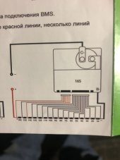
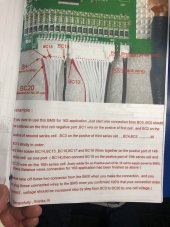
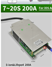
i have a JBD-AP20S006 and i need a wiring diagram in REAL ENGLISH FOR A NOVICE
The bms has a couple of connectors that are not showed on the diagram from the manufacturer. i have messed up the first BMS by crossing 2 wires. I don't want to do this again. its too costly and troublesome.
i need someone to give me the simplified version of the wiring please.
HELP!
The bms has a couple of connectors that are not showed on the diagram from the manufacturer. i have messed up the first BMS by crossing 2 wires. I don't want to do this again. its too costly and troublesome.
i need someone to give me the simplified version of the wiring please.
HELP!